Raising planter, Lowering planter, Raising planter lowering planter – Great Plains YP4025A Operator Manual User Manual
Page 32
28
YP4025A
Great Plains Manufacturing, Inc.
401-627M
2013-04-24
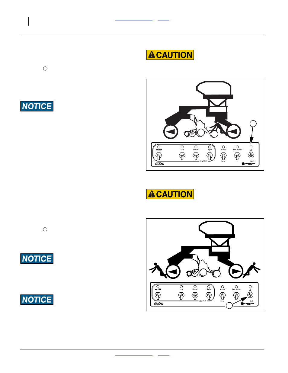
Raising Planter
Refer to Figure 24
1.
If the planter has hydraulic hitch, set the Lift/Hitch
switch
to LIFT.
Note: If the planter has the standard 3-point hitch, this
switch has no function. The hydraulic circuit is
always in Lift (Raise/Lower) mode.
2.
Move the cab lever to Extend the circuit for Lift/Hitch.
Machine Damage Risk:
On tractors with electronic timer controls for hydraulic
circuits, lift timers must be set to no more than 2 seconds
longer than needed to fully raise planter.
Do Not Set for Continuous Mode.
For transport, maintenance or storage, install lift cylinder
locks. See “Lift Cylinder Lock-Up” on page 29.
Lowering Planter
Refer to Figure 25
1.
If lift cylinder locks are installed, first fully raise the
planter, and remove the locks. See “Raising
Planter” on page 28 and “Lift Cylinder Lock-Up” on
page 29.
2.
If equipped with hydraulic hitch, set the Lift/Hitch
switch
to LIFT. On 3-point hitch, this switch has no
function and the circuit is in Lift mode at all times.
3.
Move the cab lever to Retract the circuit for Lift/Hitch.
When fully lowered, return lever to neutral.
Machine Damage Risk (Hydraulic Hitch Only):
Never lower planter while fully folded, if it is equipped with
the hydraulic tongue hitch, or machine damage can occur
unless a special procedure is followed (see page 29). A planter
with a 3-point hitch may be lowered while folded.
Machine Damage Risk:
Never lower planter while partially unfolded (with either
hitch). Wing row units can strike main transport wheels.
1
Figure 24
CFM: Raising Planter
26113
Pinch/Crush Risk:
Keep all personnel clear of center section and seed cart while
raising tool bar. The wheels move inward.
1
1
Figure 25
CFM: Lowering Planter
26113
Crushing Risk:
Keep all personnel clear of center section and seed cart while
raising tool bar. The wheels move outward.
1