Install module output harness – Great Plains 3PYPA Predelivery Manual User Manual
Page 62
58
3PYPA
Great Plains Manufacturing, Inc.
401-647Q
2012-08-08
Install Module Output Harness
This harness is only used for configurations taking
ISObus steering data, or taking native tractor steering
sensor data. It is not used with the Great Plains linear
sensor.
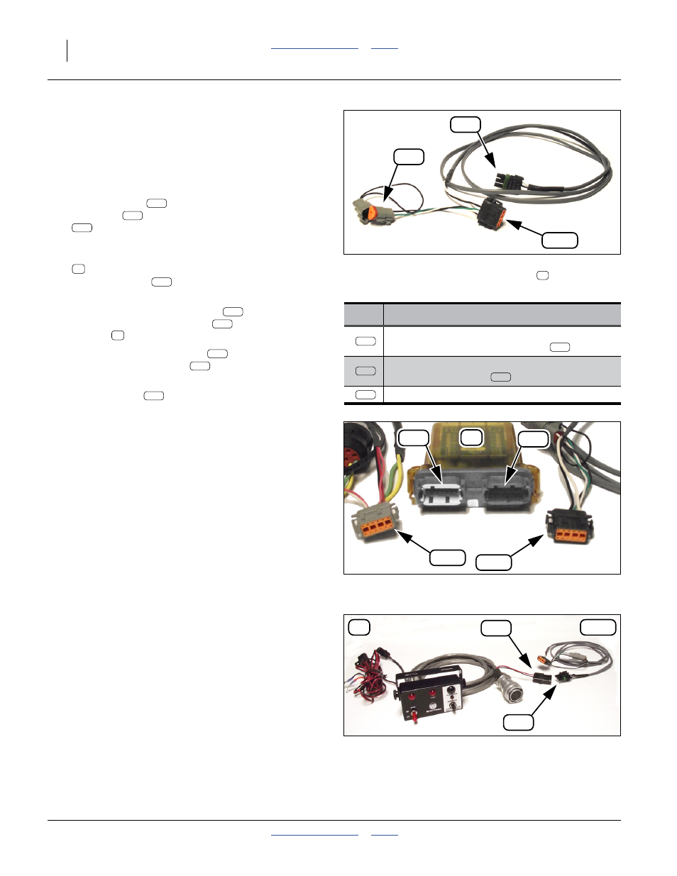
Refer to Figure 99, and Figure 100 and Figure 101
The output harness
provides a normalized PWM
steering signal
to the planter, via the sensor
lead
at the hitch connection. it also provides a USB
port form service use.
83. From the harness set:
833-547C HARNESS CANBUS STEERING MODULE
select the cable
with the Black 12-pin Deutsch
connector.
Plug the Black 12-pin Deutsch
lead into the
Black output port receptacle
of the sensor
module
.
Route the PWM signal lead
to the hitch. Mate it
to the sensor input lead
of the switchbox
harness.
The USB lead
is not used at this time. Leave
the connector capped.
Figure 99
Module Output Harness
Signal Power OUT (Black end)
31814
Lead
Function
12-pin black:
data from sensor module output
3-pin weatherpak: PWM steering data to
switch harness lead
3-pin wedge: USB
74
74K
71o
70s
74K
74u
74s
74K
70s
74
74K
74K
71o
71
70s
Figure 100
Electronic Module Ports
31812
74K
71
71o
71i
74G
Figure 101
PWN Lead to Hitch
31834
70s
70
74K