Jd ils: mount sensor – Great Plains 3PYPA Predelivery Manual User Manual
Page 53
Great Plains Manufacturing, Inc.
Tractor Steering
49
2012-08-08
401-647Q
56. Remove the sensor assembly. Check that vent hole
is unobstructed and facing down. Tighten bolt
at
top of collar to Grade 2 torque specification.
57. Turn the tractor front wheels fully to the right.
Shut off tractor.
58. Using marked holes and collar position, adjust
sensor rod until yoke and rod-end bolts align with
marked holes. Measure the overall length of the
sensor. It must be at least
3
⁄
8
inch (1 cm) shorter
than the maximum length (and can be substantially
less than that).
59. Turn the tractor front wheels fully to the right. Shut
off tractor.
60. Using marked holes and collar position, extend
sensor rod until rod end bolts align with marked
holes. Measure the overall length of the sensor. It
must be at least
3
⁄
8
inch (1 cm) longer than the
minimum length (and can be substantially more
than that).
Install to Specification Only:
If it is not possible to obtain reserve lengths of at least
3
⁄
8
inch (1 cm) at full left and right turn, have your Great
Plains dealer consult the factory. Insufficient reserve will
result in sensor damage.
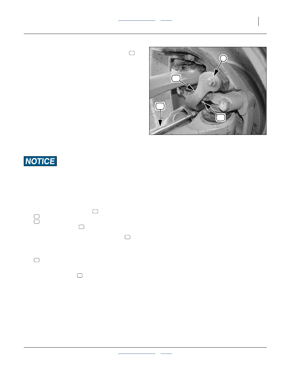
JD ILS: Mount Sensor
Refer to Figure 78, 79 (page 48) and Figure 80
61. Select the sensor assembly
, and one each:
803-255C NUT HEX NYLOCK 1/4-20
804-007C WASHER FLAT 1/4 SAE PLT
Place the flat washer
on the lower yoke bolt.
Insert the bolt, from above, through the marked hole
at the inboard bracket. Secure with lock nut
.
Tighten to allow lateral pivoting but not rocking of
gimbal assembly.
62. Select one:
803-305C NUT HEX NYLOCK 3/8-24 PLT
Insert the threaded rod-end bolt, from below,
through the marked hole in the outboard bracket.
Secure with lock nut
to Grade 2 torque spec.
Figure 80
John Deere
®
ILS Installation,
Outboard
29207
93
81
89
2
87
81
88
90
90
88
89
89