John deere® 8000 ils installation, Jd ils: mount inside (base end) bracket, Jd ils: mount outside (rod end) bracket – Great Plains 3PYPA Predelivery Manual User Manual
Page 52: Jd ils: check sensor extension, John deere, Skip to “ john deere
48
3PYPA
Great Plains Manufacturing, Inc.
401-647Q
2012-08-08
John Deere
®
8000 ILS Installation
Refer to Figure 78 and Figure 79
The sensor
is installed at the rear of the right front
axle, close to the drive shaft.
48. Turn the tractor to the left to open room to work.
JD ILS: Mount Inside (Base End) Bracket
49. Select one:
411-578D BRKT SENSOR JD SUSPEN WHL
50. Loosen the existing bolt
just aft and lower at the
inboard universal joint. Slide the bracket tab with the
open slotted hole under the bolt head. Align so the
other tab is up and horizontal. Re-secure bolt
.
JD ILS: Mount Outside (Rod End) Bracket
Refer to Figure 78 and Figure 80 on page 49
51. Select one:
411-577D BRKT SENSOR JD SUSPEN FIXED
52. Remove the existing bolt
. Using the same bolt,
secure the long tab (with the larger hole) of the
bracket
with the short tab facing forward and
right.
53. Turn the tractor front wheels straight forward.
Shut off tractor.
JD ILS: Check Sensor Extension
54. Select the sensor assembly
. Loosen the gimbal
collar
. Gently pull the sensor rod to centered
extension, as determined at step 11 on page 43,
with yoke center bolt down, and rod-end bolt up.
Note: When trial fitting, make sure sensor does not
contact any tractor components. Use alternate
mount and pivot holes as necessary to obtain
clearance.
55. Determine which bracket holes sensor fits. Mark
those holes, but do not mount the sensor at this
time. At the inboard end, use the left end tab hole
if possible. At the outboard end, use center tab
hole
if possible.
If sensor is too short, move collar toward connector
end (base) of sensor. Do not block vent hole. If
sensor is still too short, use alternate hole
at
outboard bracket.
If sensor is too long, move collar toward rod end of
sensor.
Note holes and collar position with a marker.
Note: Sensor will tilt up slight from inboard to outboard.
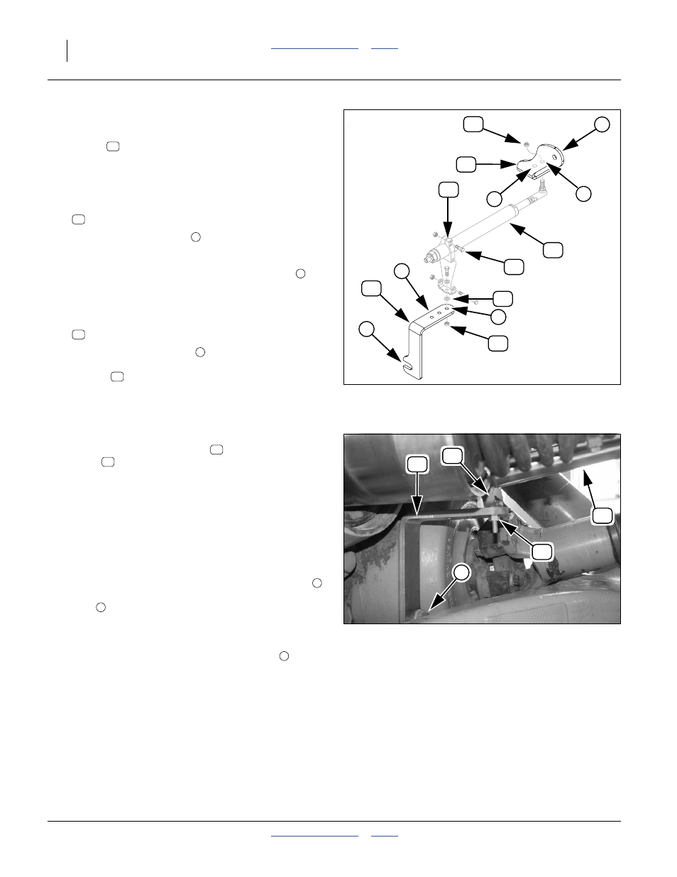
Figure 78
John Deere
®
ILS Components
29202
81
94
3
93
5
88
90
84
89
6
8
87
4
9
81
94
a
a
93
a
93
Figure 79
John Deere
®
ILS Installation,
Inboard
29206
a
81
88
94
84
81
84
5
8
9