Install left and right caster arms, Install caster wheels – Great Plains 3PYPA Predelivery Manual User Manual
Page 28
24
3PYPA
Great Plains Manufacturing, Inc.
401-647Q
2012-08-08
Install Left and Right Caster Arms
Refer to Figure 38 and Figure 39
43. Carefully secure one caster arm to a lift or hoist
capable of holding the arm with the pivot hole
vertical, and remaining clear of the seed structure
while positioning the arm.
44. At the cart, remove and save one set of:
803-026C NUT LOCK 3/4-10 PLT
(not shown)
802-360C HHCS 3/4-10X6 1/2 GR5
804-102C PIVOT THRUST WASHER
Coat the spindle with anti-seize compound.
45. Align the arm under the spindle. Place the thrust
washer
on the spindle before the spindle
contacts the arm.
46. Fully raise the arm on the spindle. If the spindle
rises, tap it down with a rubber mallet.
47. Align the holes in the arm and the spindle, and
secure the arm to the spindle with the cross-bolt
and nut
.
48. Repeat steps to install other caster arm.
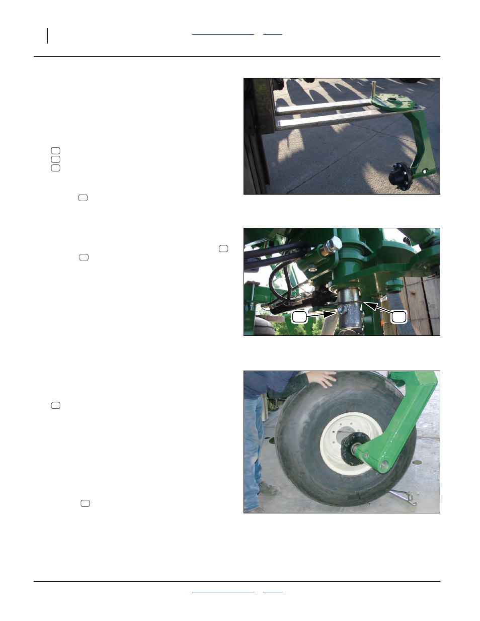
Install Caster Wheels
Refer to Figure 40 (tie rods not installed)
49. Remove and save the lug nuts (not shown)
803-219C NUT LUG 5/8-18 X 90 DEG PLT
from the right caster hub.
50. Roll one of the wheel assemblies (they are identical)
up to the caster arm. Orient the side with the valve
stem away from the hub (toward seed structure
center).
51. Adjust the elevation of the seed structure so that the
wheel just fits over the threaded studs on the hub.
This eases the assembly.
52. Seat the wheel on the hub and secure with saved
lug nuts
.
53. Rotate caster until the 1
1
⁄
4
inch diameter alignment
pin holes in the caster top plate and the steering
arm align. Install the alignment from the bottom and
lock in place with
1
⁄
2
inch bolt and nut supplied.
Figure 38
Move Caster Arm to Spindle
31693
48
40
61
61
Figure 39
Cross Bolt and Thrust Washer
31694
61
40
40
48
Figure 40
Install Caster Wheels
31691
51
51