John deere® tracked native sensor harness, John deere, Tracked native – Great Plains 3PYPA Predelivery Manual User Manual
Page 60
56
3PYPA
Great Plains Manufacturing, Inc.
401-647Q
2012-08-08
John Deere
®
Tracked Native Sensor
Harness
Optional adaptor harness
for John Deere
®
tracked
tractors is necessary when the tractor wheel angle signal
cannot be obtained from the CANbus on the tractor.
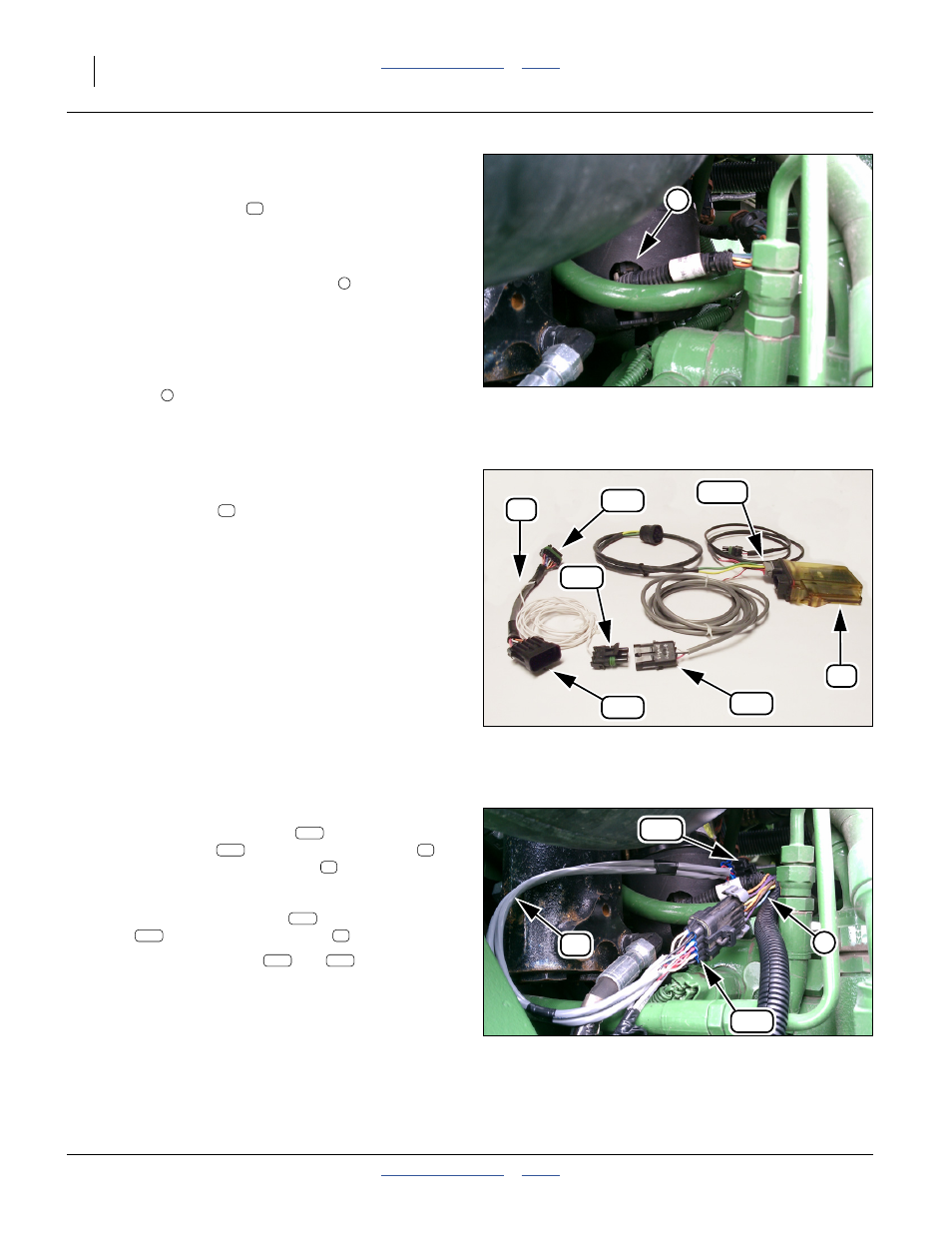
Refer to Figure 94
75. Locate the Steering Angle Sensor
on the bottom of the steering column, and is
accessible from the right side of the tractor just in
front of the cab.
Refer to Figure 96
76. Disconnect the sensor lead (not shown) and tractor
harness
.
Refer to Figure 95 and Figure 96
77. Reconnect the disconnected leads using the
adaptor harness
.
Refer to Figure 95
78. Route the sensor input lead
of the gray master
module harness
from the sensor module
in
the cab, to the adaptor harness
just installed at
Mate the sensor input lead
to the sensor tap
lead
on the adaptor harness
.
79. Dress the sensor leads
and
along existing
harnesses, tubing, hoses and tractor fittings. Allow
slack near moving parts, routing through pivot
center-lines where possible. Avoid hot parts. Protect
the harness against strikes from brush and tall
stubble. Secure with cable ties.
Continue at “Install Module Output Harness” on
page 58.
Figure 94
John Deere
®
Tracked Tractor
Steering Sensor Location
31850
1
73
2
Figure 95
John Deere
®
Tracked Tractors
Adaptor Harness
31837
73
74r
71
74G
73
Figure 96
John Deere
®
Tracked Tractor
Adaptor Harness Installed
31829
2
73
74r
74G
71
73
74r
73
74r