Raven setup – Great Plains TSF1260 Operator Manual User Manual
Page 32
28
TSF1060 and TSF1260
Great Plains Manufacturing, Inc.
500-642M
01/12/2012
The operator sets the target volume per area to be
sprayed and the SCS 440 automatically maintains the
flow regardless of vehicle speed or gear selection. A
manual override switch allows the operator to manually
control flow for system check-out and spot spraying.
Actual volume per area being applied is displayed at all
times. The SCS 440 additionally functions as an area
monitor, speed monitor and volume totalizer.
Raven Setup
Current TSF1060 and TSF1260 sprayers include a
Raven SCS 440 controller as standard equipment. The
controller needs to be installed in the tractor cab, and
cables run to the sprayer, speed sensor and battery prior
to first use. Consult the included Raven manual for instal-
lation instructions.
The SCS 440 requires some initial data about your
sprayer and tractor prior to first use.
This data is retained as long as the SCS 440 remains
connected to battery power. If power is removed for elec-
trical work, long term tractor parking or welding, the data
is lost and must be re-entered.
Consult the Raven manual for display interpretation and
keyboard procedures.
The following data is needed for Raven setup:
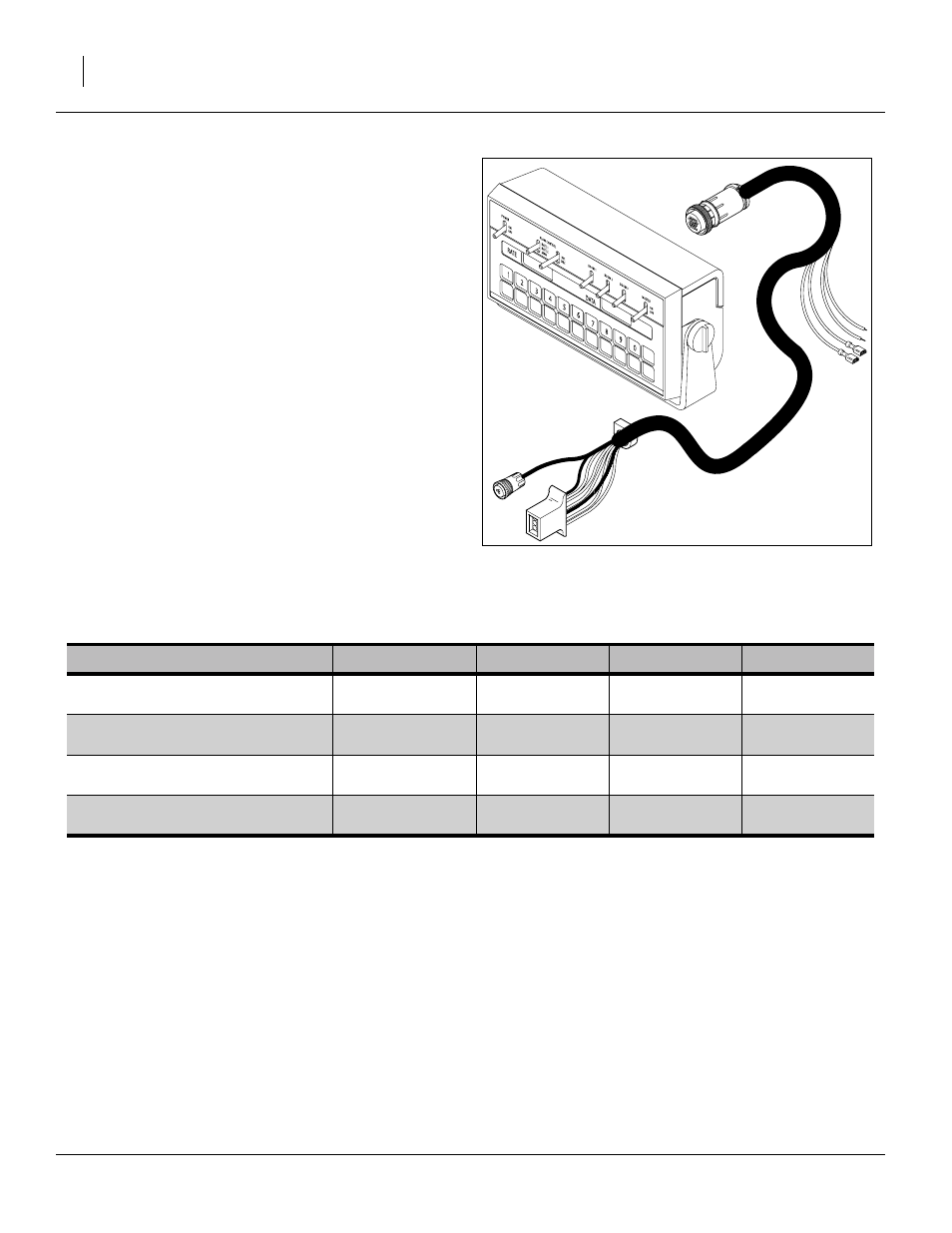
Figure 23
Raven SCS 440 and Cab Cable
28124
Model
Description
BOOM CAL
SPEED CAL
METER CAL
VALVE CAL
TSF-1060-2530 1000 Gallon 60
foot 30in spacing
750in (1905 cm)
Cable Tag
a
Body Label
b
TSF-1060-3620 1000 Gallon 60
foot 20in spacing
720 in (1828 cm)
Cable Tag
TSF-1260-2530 1250 Gallon 60
foot 30in spacing
750in (1905 cm)
Cable Tag
TSF-1260-3620 1250 Gallon 60
foot 20in spacing
720 in (1828 cm)
Cable Tag
a. This value is printed on a durable tag attached to the meter cable.
b. This value, typically “2123”, is printed on the label on the valve body.