Hydraulic pump setup, Ace pump flow limiter (option), Flow limiter installation – Great Plains TSF1260 Operator Manual User Manual
Page 30: Setting pump rate
26
TSF1060 and TSF1260
Great Plains Manufacturing, Inc.
500-642M
01/12/2012
Hydraulic Pump Setup
The hydraulic motor used on all liquid pumps is a 7 gpm
(23 liter/min.) motor. If the tractor used on the sprayer
does not have the capabilities to adjust the remotes
down to this flow, then a Hydraulic Flow Divider Kit must
be installed so that flow can be controlled to prevent
operating the pump at excessive speeds. See a Great
Plains dealer for more information.
1.
Connect the hydraulic pump to the tractor remotes.
See “Hydraulic Pump Hookup” on page 21 for
details. If no limiter is required, skip to step 7.
DO NOT move the hydraulic lever into the neutral position
while the hydraulic pump is running. To do so may cause dam-
age to the hydraulic pump.
Ace Pump Flow Limiter (Option)
The flow limiter (Great Plains part number 829-125C) is
a hydraulic device designed to shut off the flow of
hydraulic oil when a specified flow is exceeded. On trac-
tors with LOAD SENSING (LS) Closed Center hydraulic
systems, this device limits the flow of oil to the Ace motor
and prevents failures due to misapplication.
Newer Case-IH, John Deere, New Holland, and CAT
tractors, present a great potential to turn the motors
beyond their rated speeds. Flows out of the hydraulic
valves can exceed 20 gpm while the motors are rated at
4-11 gpm. The flow limiter protects the Ace motor by
shutting off when hydraulic flows exceed the motor’s
capacity.
The flow limiter should not be used on OPEN Center or
PRESSURE COMPENSATING Closed Center hydraulic
systems. The flow limiter should not be used with a
restrictor orifice.
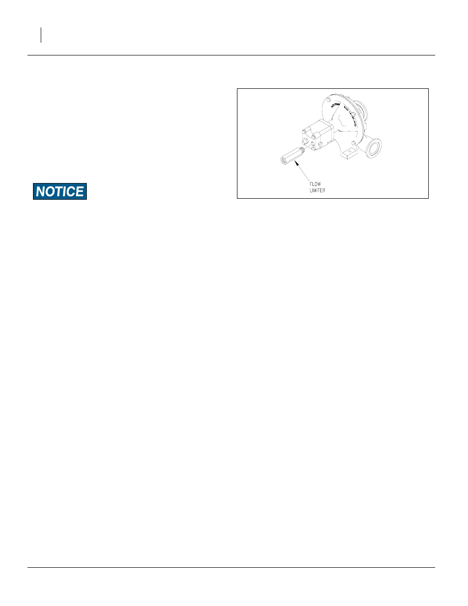
Flow Limiter Installation
2.
Install the flow limiter in the inlet port of the Ace
motor.
3.
Shut off boom and agitation valves on the sprayer to
deadhead the sprayer pump flow.
4.
Adjust the flow control on the tractor to the minimum
flow setting (typically a “turtle” icon).
5.
Move the hydraulic lever to the “Lower/Retract” posi-
tion.
6.
Adjust the flow control on the tractor until the sprayer
system deadhead pressure is 80 psi.
Note: If the flow limiter stops the flow of oil to the motor:
6a) Move the hydraulic lever to the “Neutral” posi-
tion. This removes the oil pressure from the flow
limiter and allows it to reset.
6b) Adjust the flow control to a lower flow position.
Setting Pump Rate
7.
To determine the correct setting of the flow rate, start
out with the hydraulic flow control valve at minimum
flow for the outlets that operate the pump.
8.
With water in the sprayer tank and in the pump, place
the hydraulic lever in the float position.
9.
Open up the sprayer flow control valve to its maxi-
mum setting.
10. Start the tractor and engage the pump by placing the
hydraulic lever in the down (forward) position.
11. Once the system builds pressure, close the agitation
valve, shut off the boom section switches, and close
the throttling valves (if applicable).
12. The pump is now at dead head pressure and the
hydraulic control valve must be adjusted so that the
spray pressure reaches 80 PSI maximum on the
nozzle pressure gauge. This process should be done
with the tractor throttle set at normal operating
speed. Mark this setting on the hydraulic control
valve for future reference.
13. Open up the agitation valve and reset the throttling
valve (if applicable). See “Manual Throttle Valve” on
page 30.
Figure 21
Ace Pump Flow Limiter
23395