Operator controls – Wheatheart X Series 13 Augers User Manual
Page 88
6. O
PERATION
W
HEATHEART
- X13 S
ERIES
A
UGERS
6.2. O
PERATOR
C
ONTROLS
X1374, X1384, X1394
88
30787 R1
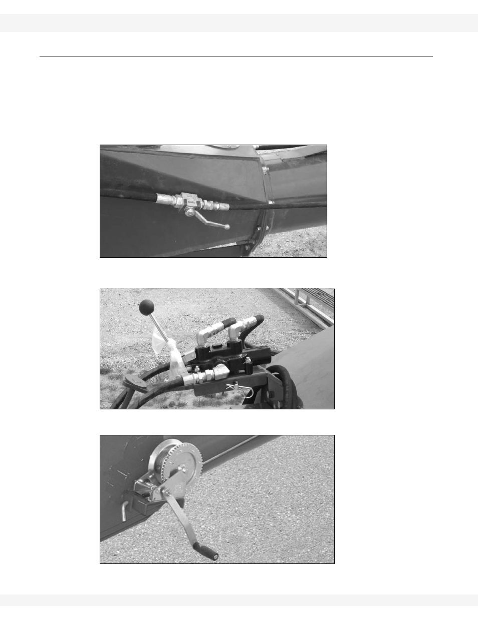
6.2. OPERATOR CONTROLS
Figure 6.1 shows the hydraulic shut-off valve for the main auger tube hydraulic
lift cylinders.
Figure 6.2 and Figure 6.3 (respectively) show hydraulic winch and manual winch
controls for lifting and lowering the hopper to and from transport position.
For locations for PTO and hydraulic supply controls, please refer to the operating
manual for the attached tractor.
Figure 6.1 Main Auger Tube Lift Shut-off Valve
Figure 6.2 Hydraulic Hopper Winch Control (Optional)
Figure 6.3 Manual Hopper Winch