Auger tube truss assembly, X130-74 auger tube truss assembly – Wheatheart X Series 13 Augers User Manual
Page 35
W
HEATHEART
- X13 S
ERIES
A
UGERS
3. A
SSEMBLY
X1374, X1384, X1394
3.10. A
UGER
T
UBE
T
RUSS
A
SSEMBLY
30787 R1
35
3.10. AUGER TUBE TRUSS ASSEMBLY
• X130-74 augers use a double cable truss on the top of the auger tube “X130-
74 Auger Tube Truss Assembly” on page 35).
• X130-84 and X130-94 augers use a combination of rigid tube trussing on top
of the auger tube and cable trussing on the sides of the auger tube (see
“X130-84/X130-94 Auger Tube Truss Assembly” on page 40).
3.10.1. X130-74 A
UGER
T
UBE
T
RUSS
A
SSEMBLY
I
NSTALL
THE
X130-74 C
ABLE
B
RIDGES
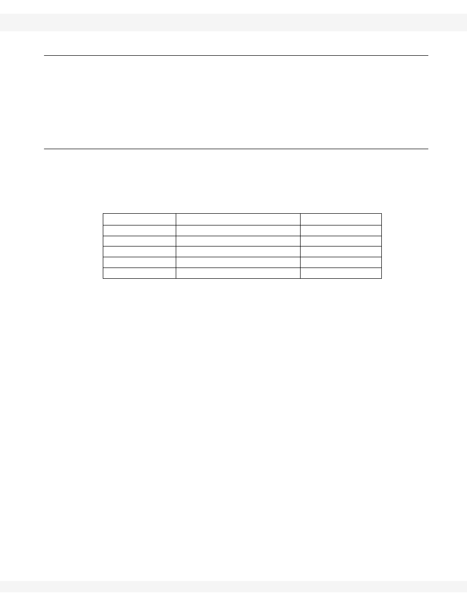
See Table 3.7. for a list of parts required to install the X130-74 cable bridges.
See Figure 3.12 for a detailed diagram.
1. Fasten the three truss towers to the provided brackets (welded to the
appropriate tube sections):
a. Position the high truss tower in the centre position, and position the low
truss towers toward the spout and intake ends.
b. Use two 7/16” x 1-1/4” GR8 bolts and 7/16” locknuts to fasten each cable
bridge in place.
2. Install the truss cable attach bracket as shown in the diagram, using two
7/16” x 1-1/4” GR8 bolts and 7/16” locknuts.
Table 3.7. Parts Required, Installing X130-74 Cable Bridges
Part Number
Description
Amount
20017
High truss tower
1
18988WH
Low truss towers
2
20105
Truss cable attach bracket
1
18698
7/16” x 1-1/4” GR8 bolts
8
17593
7/16” locknut
8