Prefix 80 series exit device, System wiring examples (continued) 9 – SARGENT 57 - Delayed Egress User Manual
Page 16
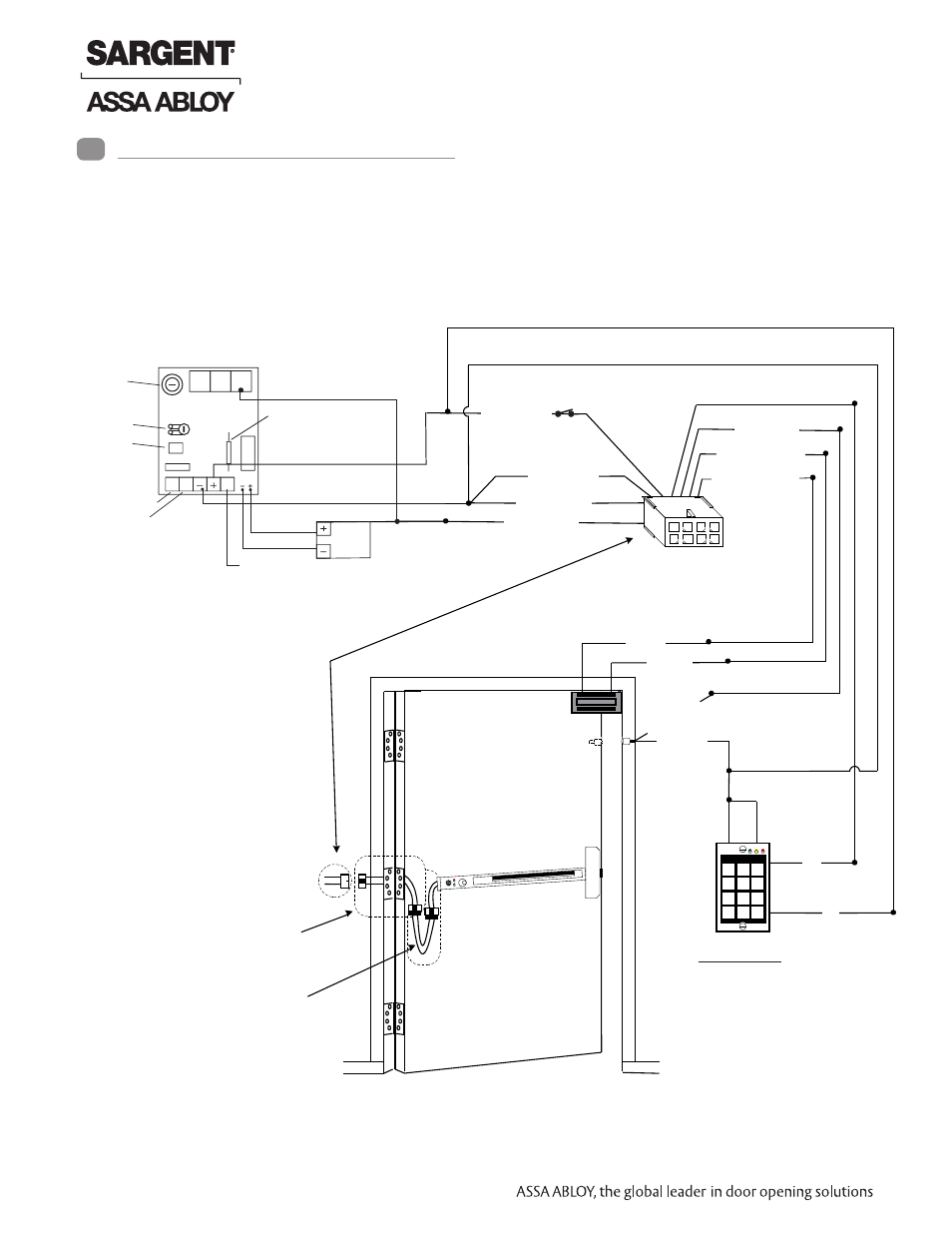
Sample Wiring #2 – 57- Exit Device with inside Keypad,
Fire Alarm, Door Status and Remote Horn
A valid code entry at the 4291 (Inside) keypad shunts the 57- exit device and allows egress for a time period programmable
at the keypad. During a fire alarm condition, the contact opens which de-energizes the external electromagnet and allows im-
mediate egress. When the rail is armed and the door is forced open, the 3287 door status switch signals the rail sounding the
rail alarm.
System Wiring Examples (Continued)
9
3520 24VDC 1.0AMP Regulated and Filtered Power Supply
5, Orange (EI)
Red
(+24),
2
6, Blue (DS)
Normally Closed Fire
Alarm Contact
(If Required)
7, Brown (Mag
-
)
Black
(
-
24),
1
Green (EG), 4
2
4
8
7
6
3 1
5
Pigtail harness
assembly with
8-pin connector
Red (+)
Black (-)
1584
Electromagnetic
Green(NC)
Lock
White (C)
3287
Door Status
Switch
(
-
)
Plug pigtail harness
connector into
C
8-pin hinge connector
at frame side
NO
1 2 3
4291
Keypad
of door
4 5 6
7 8 9
(Inside)
57- 80 Series Rail
with 8-pin connector
0 #
(+)
*
Electric Hinge with
8-pin hinge connector
Raceway harness with
8 & 4-pin connectors.
The 4-pin connectors are not
used here.
Line voltage
fuse (1 AMP)
Connector to
power on LED
HOT
110-120 VAC
NEUT
GND
AC
F
Low voltage AC
From transformer
AC
DC DC
Output
NOTE: This drawing shows the
BPS Series. The PM Series
has no line voltage input, fuse
or connector to power on LED
2.5 AMP polyswitch breaker
Red
Black
Unconnected
terminal for
switch hookup
Battery pack
Voltage adjust for
battery backup
8, Yellow (Mag +)
White (RR), 3
Wiring Notes:
1. Rail, raceway, electric hinge and
pigtail 8-pin connector terminations
and wire colors all match.
2. Tape or cap off ends of unused pigtail
wires (not shown) to ensure that they
do not short.
3. A fire alarm tie-in is required on fire
rated openings.
4. The fire alarm contact (when
required) must be wired to drop
24VDC power to rail. In this case,
terminate fire alarm contact between
the red (+ 24VDC) wire and supply +
24VDC output.
16 1-800-810-WIRE • www.sargentlock.com • A7743C
Copyright © 2013, Sargen
t Manufacturing Company
, an A
SS
A AB
LO
Y G
roup company
. All right
s reser
ved
.
Reproductions in whole or in par
t without express writ
ten permission of Sargen
t Manufacturing Company is prohibited
.
04/15/13
57- Prefix 80 Series Exit Device
- FM8700 Surface Vertical Rod Exit Device PR8700 Center & Top Latch Surface Vertical Rods for Pair of Doors PP8700 Center & Top Latch Surface Vertical Rods for Pair of Doors HC8700 Hurricane Code Surface Vertical Rod Exit Device NB8700 Top Latch Surface Vertical Rod 8700 Surface Vertical Rod Exit Device SP8600 Center & Top Latch Concealed Vertical Rods PR8600 Center & Top Latch Concealed Vertical Rods PP8600 Center & Top Latch Concealed Vertical Rods LR8600 Low Profile Center & Top Latch Concealed Vertical Rod Exit Devices LP8600 Low Profile Center & Top Latch Concealed Vertical Rod Exit Devices NB-WD8600 Concealed Vertical Rod Exit Device for Wood Doors WD8600 Concealed Vertical Rod Exit Device for Wood Doors NB-MD8600 Concealed Vertical Rod Exit Device for Metal Doors MD8600 Concealed Vertical Rod Exit Device for Metal Doors NB-MD8400 Series Narrow Style Concealed Vertical Rod MD8400 Series Narrow Style Concealed Vertical Rod LS8600 Low Profile Center & Top Latch Concealed Vertical Rods WS8900 Mortise Lock 8900 Mortise Lock Exit Device 8300 8888 Reversible Rim Exit Device 8800 Rim Exit Device 8500 Narrow Design Rim Exit Device HC8800 Rim Exit Device