Profile series v.g1 mortise lock, Step #6, Fig. 1 fig. 2 fig. 3 – SARGENT Profile Series v.G1.5 Mortise Locks User Manual
Page 9
7
800-810-WIRE (9473) • www.sargentlock.com • A7756A
Profile Series v.G1 Mortise Lock
Copyright © 2006, 2008, Sargent Manufacturing Company
, an A
SSA ABL
O
Y
Group company
. All rights reserved.
Reproduction in whole or in part without the express written permission of Sargent Manufacturing Company is prohibited.
Mortise lockbody
connector and wire
Gasket
82-0500
Outside of
door
8-32 x 1-1/4"
Flat Head
Screw
Keypad
harness
Ground
wire
Motor
harness
Inside of
door
With
Deadbolt
Without
Deadbolt
RED
Black
Green
Green
Red
Black
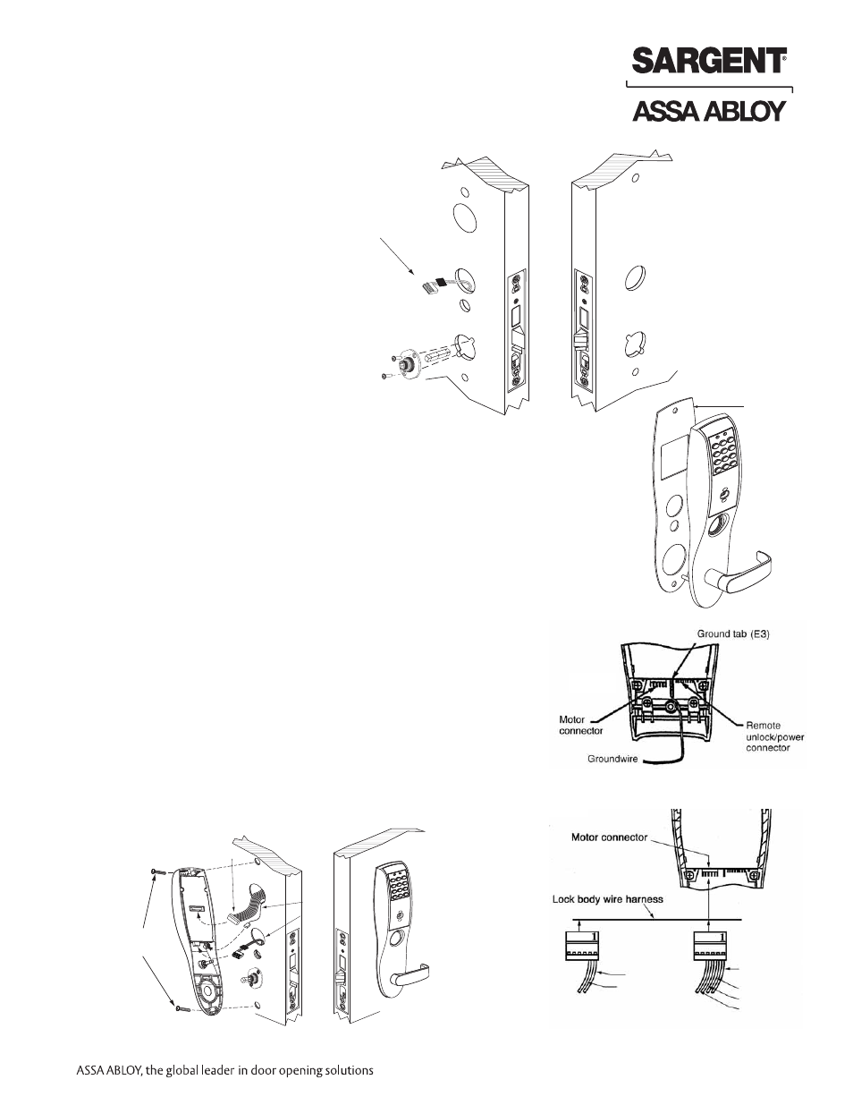
6.
Connect ground wire to terminal E3 (Fig. 1), keypad ribbon
cable connector to controller (Fig. 2), and ET motor harness to
motor connector (Fig. 3).
7.
Place extra wire inside door hole or outside escutcheon being
careful not to pinch wires
NOTE: Connectors go on only one way, do not offset connector and
be sure they are completely seated
8.
Insert #8-32 x 1-1/4" screws through inside escutcheon and thread
into outside escutcheon. Straighten (Ref. Fig. 2) escutcheons and
tighten securely.
NOTE: For RF Technology versions (G1-TU, G1-TP, G1-TA) refer to
Section 8 to install through bolt screws.
Step #5 – Installation of Outside/Inside Escutcheon
& Lever Assembly
NOTE: For exterior applications, gasket (82-0500)
should be used to seal between escutcheon and
outside door surface
1A.
For 12- fire rated devices,
feed keypad ribbon cable
connector and ground wire
from outside of door through
gasket and fire stop plate hole
1B.
For non-12- exit devices, feed keypad ribbon
cable connector and ground wire through
gasket then through conduit hole in door
2.
With outside lever horizontal, insert
mounting posts through door and
lock body. Make certain the lever
spindle is properly engaged in lock.
3.
Secure inside adapter and plate assembly by
threading screws into mounting posts of
outside lever assembly
4.
Tighten retaining nut by hand, back off slightly
until star pattern lines up with square lever
assembly corners
5.
Insert spindle into square hole of adapter plate
Step #6
Fig. 1
Fig. 2
Fig. 3
For RF Technology
see Section 8