Profile series v.g1 mortise lock, Step #8 – installation of cylinder, Fig. 1 fig. 2 – SARGENT Profile Series v.G1.5 Mortise Locks User Manual
Page 10: Fig. 1 fig. 3 fig. 2
8
800-810-WIRE (9473) • www.sargentlock.com • A7756A
Profile Series v.G1 Mortise Lock
Copyright © 2006, 2008, Sargent Manufacturing Company
, an A
SSA ABL
O
Y
Group company
. All rights reserved.
Reproduction in whole or in part without the express written permission of Sargent Manufacturing Company is prohibited.
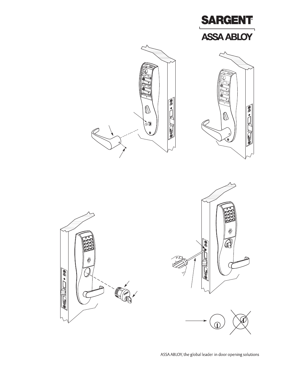
Step #7 – Installation of Inside Lever and Outside Cylinder
Inside of
door
•
Set
screw
Inside lever
Spindle
1. Put the turn lever in the horizontal position
(Ref. Fig. 1).
2. Slide lever handle onto spindle until fully seated
(as shown in Fig. 2). Be sure handle is horizontal
and facing to the rear of the door
3. Tighten the set screw securely with 1/8" hex wrench
Fig. 1
Fig. 2
Step #8 – Installation of Cylinder
1. Align cylinder (as shown in Fig. 1).
2. Screw cylinder into lockbody unit (Ref. Fig. 3 for cylinder orientation).
3. Tighten the set screw to prevent unscrewing of the cylinder (Ref. Fig. 2).
4. Turn the keyway in the cylinder to make certain that the locking mechanism
functions correctly.
Outside of door
Type 43 Mortise
cylinder ONLY
Key
Phillips
screwdriver
Set screw
Fig. 1
Fig. 3
Fig. 2
SARGENT
SARGENT
Note: Key and
cylinder must be
rotated as shown
Correct
Incorrect