Profile series v.g1 cylindrical lock, Frame preparation for strike, Latchbolt and fire stop plate installation – SARGENT Profile Series v.G1.5 Cylindrical Locks User Manual
Page 7
5
800-810-WIRE (9473) • www.sargentlock.com • A7755A
Profile Series v.G1 Cylindrical Lock
Copyright © 2004, 2008, Sargent Manufacturing Company
, an A
SSA ABL
O
Y
Group company
. All rights reserved.
Reproduction in whole or in part without the express written permission of Sargent Manufacturing Company is prohibited.
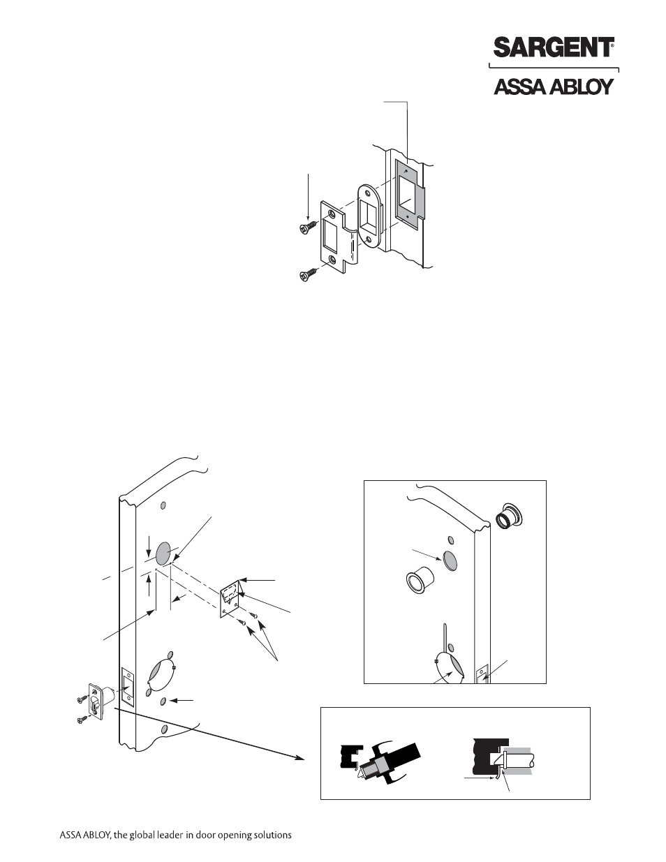
3. Frame Preparation for Strike
Non Fire Rated Exterior Doors–
Install Weather Conduit (P/N 52-2847)
as shown below
4. Latchbolt and Fire Stop Plate Installation
1. Install latch with beveled bolt facing the strike.
2. Attach with two screws but DO NOT tighten completely at this time.
3. Attach Fire Stop Plate with two screws.
Note: Required for all Fire Rated doors
Centerline of
latch front and
strike
Screws (2)
#8-32 x 3/4"
1-1/2"
(2) 1/8" Dia. holes
required
7/8"
Fire
stop plate
Through-bolt
hole (2)
(2) Self tapping
screws #8 x 1/2"
long for wood
& metal doors
Slot
CL of
1-1/2" Dia.
IMPORTANT: Latch bevel must match door bevel and
deadlocking latch must stop on strike when door is closed
Latchbolt
door prep
Inside
of door
Hole for ribbon
cable from keypad
to controller
Fire Rated Doors– Install Fire
Stop Plate (P/N 52-0033)
as shown below
Strike