Profile series v.g1 cylindrical lock – SARGENT Profile Series v.G1.5 Cylindrical Locks User Manual
Page 10
Outside of
door
Ground
wire
8-32 Flat head
Weather
Seal
Gasket
Latch
screws
Cylinder
spacer
Ribbon
cable with
connector
Outside
Escutcheon
Fire stop
plate
Weather
seal gasket
8
800-810-WIRE (9473) • www.sargentlock.com • A7755A
Profile Series v.G1 Cylindrical Lock
Copyright © 2004, 2008, Sargent Manufacturing Company
, an A
SSA ABL
O
Y
Group company
. All rights reserved.
Reproduction in whole or in part without the express written permission of Sargent Manufacturing Company is prohibited.
NOTE: For exterior applications, use weather seal gasket part
# (10-0649) between escutcheon and outside door surface
1A. For fire rated doors only feed ribbon cable connector and
ground wire from outside of door through weather seal gasket
(if used) then fire stop plate.
1B. For non-fire rated doors only, feed ribbon cable connector
and ground wire from outside of door through weather seal
gasket (if used), then conduit sleeve in door (not shown).*
2.
Slide the outside escutcheon over the lock, and hold
the escutcheon to the door surface
3.
Verify white plastic cylinder spacer is inserted into horizontal
slot of lockbody.*
4.
Slide the outside lever onto tube with key horizontal
(toward latch). Rotate key 45 degress clockwise.
5.
Push lever until lever catch is engaged
Inside lever
Inside
of door
Inside rose
8-32 Flat head
screw
(C) Lockbody
harness
(E) Keypad
harness
(A)
Ground
wire
(F) Controller
connector
Latch
screws
spacer
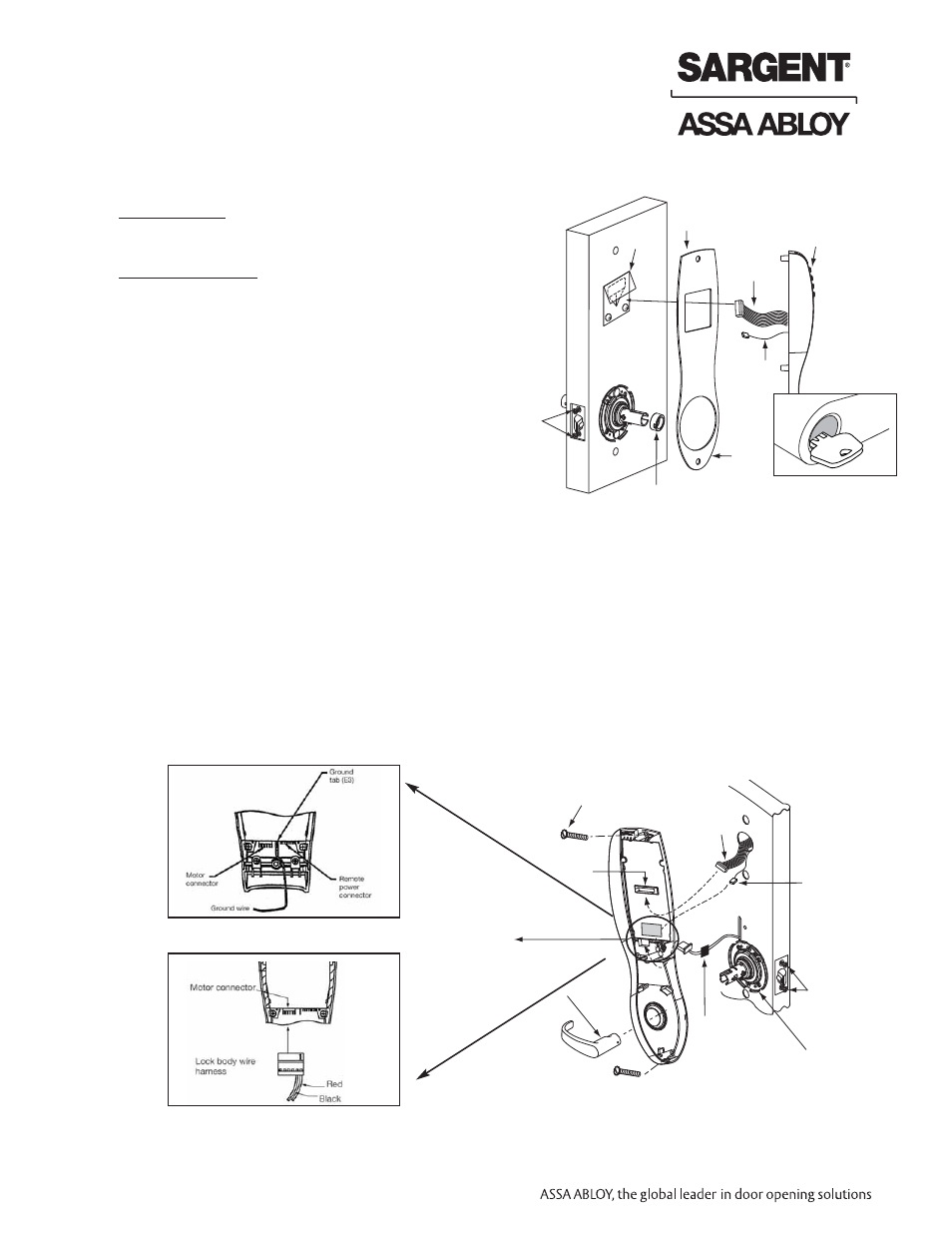
8. Installation of Outside Escutcheon and Lever
9. Inside Escutcheon and Lever
1. Remove black battery cover from the escutcheon with security wrench (provided).
2. Connect ground wire to terminal E3 (Fig. 1), connect keypad harness (Fig. 2) to controller, and connect lock
body motor harness (Fig. 3) to motor connector.
3. Feed all excess wire through inside door hole and/into outside escutcheon cavity, being careful not to pinch wires.
NOTE: Connectors go on only one way, do not offset connector and be sure they are completely sealed.
4. Insert two #8-32 screws (Fig. 2) through top and bottom of inside escutcheon and thread into outside escutcheon.
Straighten escutcheons and tighten securely, being careful to avoid pinching wires.
NOTE: For RF Technology versions (G1-TU, G1-TP, G1-TA), refer to Section 8 to install through-bolt screws.
5. Slide the Inside Lever onto the tube.
6. Tighten two latch screws completely.
Figure 1
Figure 3
Figure 2
* NOT SHOWN