Passport 1000 pg mortise lock, 3 - installation of lock body – SARGENT Passport 1000 PG Mortise Locks User Manual
Page 9
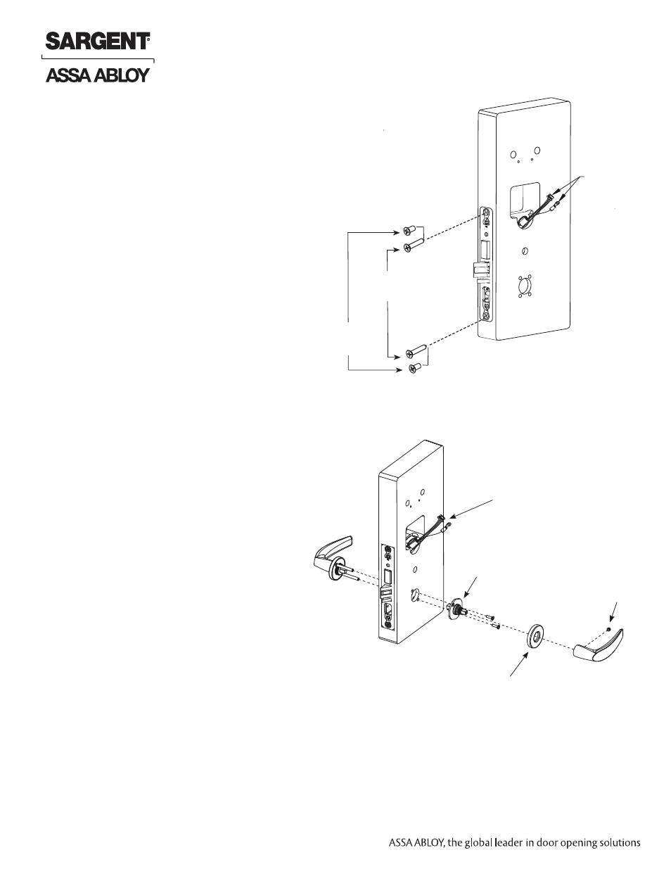
Fig. 3A
Fig. 4A
Align through bolt posts on outside
lever assembly with door prepped holes
(Fig.4A).
1. Slide the outside lever assembly with
spindle though the door and lock
body.
2. Secure lever assembly with the inside
adapter plate with (2) screws:
DO NOT TIGHTEN.
3. Securely tighten the lock body screws on
edge of door.
5. Place rose over inside adapter and
tighten clockwise.
6. Fasten inside lever to inside adapter and
tighten lever set screw snugly.
Mortise lock body
connector and
grounding lug
3 - Installation of Lock Body
4. Securely tighten both inside adapter screws.
1. Insert lock body into mortised cutout (Fig. 3A).
Connector and wires must be coiled within
retaining ring in cylinder hole.
2. Push cable and connector through
perforated
sticker* on non-cylinder side of hole.
*
Note: If hand of lock body has changed, sticker will
have been removed (see previous 2).
3. Hold lock body loosely in place with (2) lock
body screws.
(2) #12-24 x 1/2”
Flat Head Screws
(Metal Doors)
(2) #12 x 1-1/4”
Flat Head Screws
(Metal Doors)
Note: Do not completely tighten
screws at this time.
4 - Installation of Outside & Inside
Lever Assembly Lock Body
Mortise Lock Body
Connector and Ground Ring
Terminal
Inside Adapter Plate
Rose
Set Screw
Outside Lever
Assembly
9
A7807C
Copyright © 2012, Sargent Manufacturing Company
, an ASSA ABLOY Group company
. All rights reser
ved.
Reproductions in whole or in part without express written permission of Sargent Manufacturing Company is prohibited.
10/31/12
Passport 1000 PG Mortise Lock