Kp series keypad mortise lock, Step #3 – install lock body – SARGENT Keypad Exit Devices User Manual
Page 10
10 1-800-810-WIRE • www.sargentlock.com • A7373C
Copyright © 2014, Sargent Manufacturing Company
, an ASSA ABLOY Group company
. All rights reser
ved.
Reproductions in whole or in part without express written permission of Sargent Manufacturing Company is prohibited.
03/31/14
KP Series
Keypad Mortise Lock
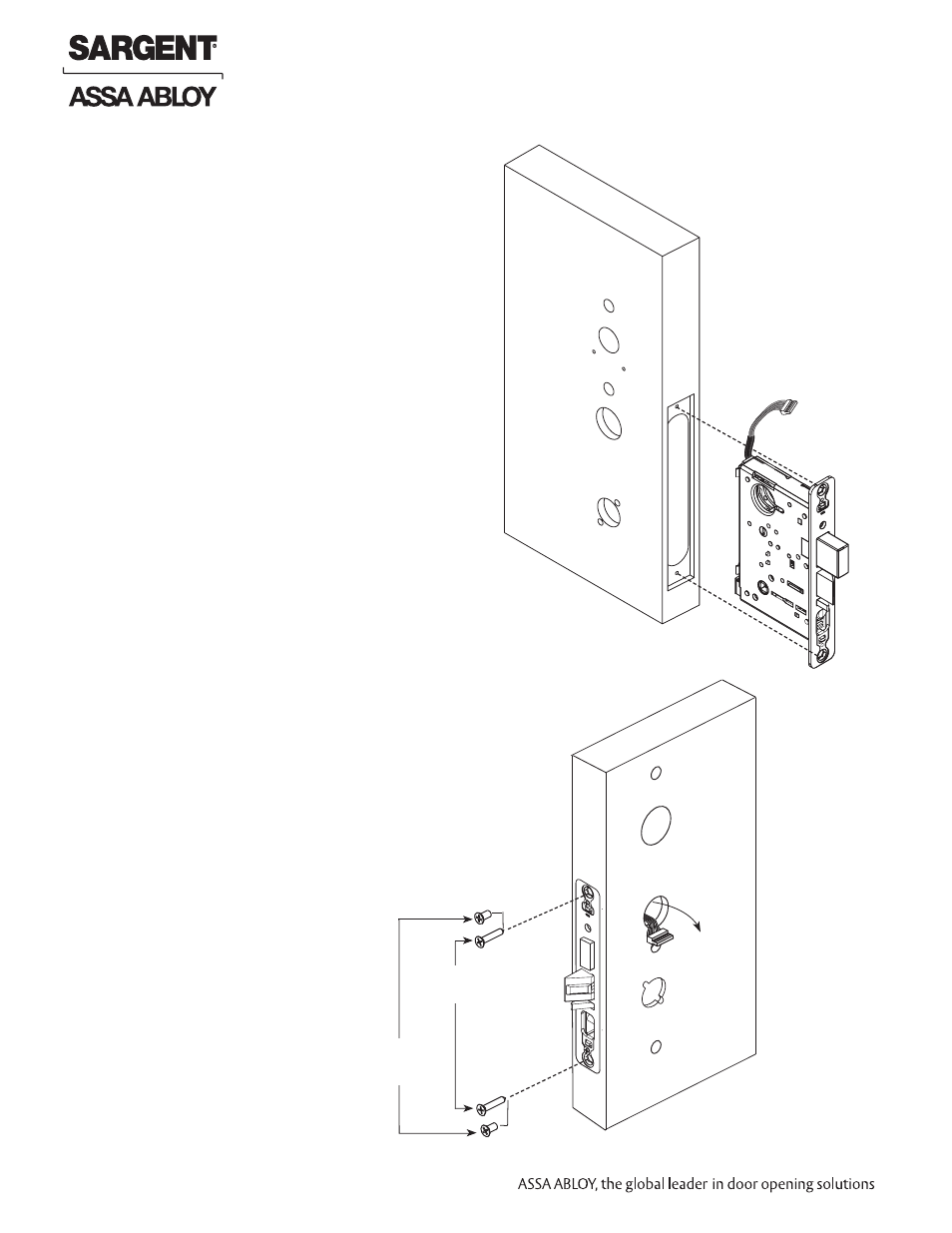
1. Insert lock body into mortised cutout (Fig. 3A).
Step #3 – Install Lock Body
(2) #12-24 x 1/2”
Flat Head Screws
(Metal Doors)
(2) #12 x 1-1/4”
Flat Head Screws
(Metal Doors)
Fig. 3A
Harness exits
Non-Cylinder side
Fig. 3B
Outside of Door
Inside of Door
2. Hold lock body loosely in place with (2) lock
body screws.
Note: Do not completely tighten screws at this time.
This manual is related to the following products: