Operating the at10.1 – Exide Technologies Section 94.20 User Manual
Page 42
OPERATING THE AT10.1
2.3.8. Using the Low Level Detector (LLD)
The AT10.1 battery charger is equipped with a summary alarm safety
override circuit. This feature forces the summary alarm (common alarm)
relay contact to transfer, sending an alarm, even if there is a catastrophic
failure of the charger's control circuitry. A low battery voltage triggers the
safety circuit.
Main control circuit board hardware, not software, maintains the low level
detect circuit. Therefore, to remotely monitor this alarm, user connections
must be made at TB3. The summary alarm contacts on the auxiliary alarm
relay pc board at TB4 will not signal a low level detect alarm.
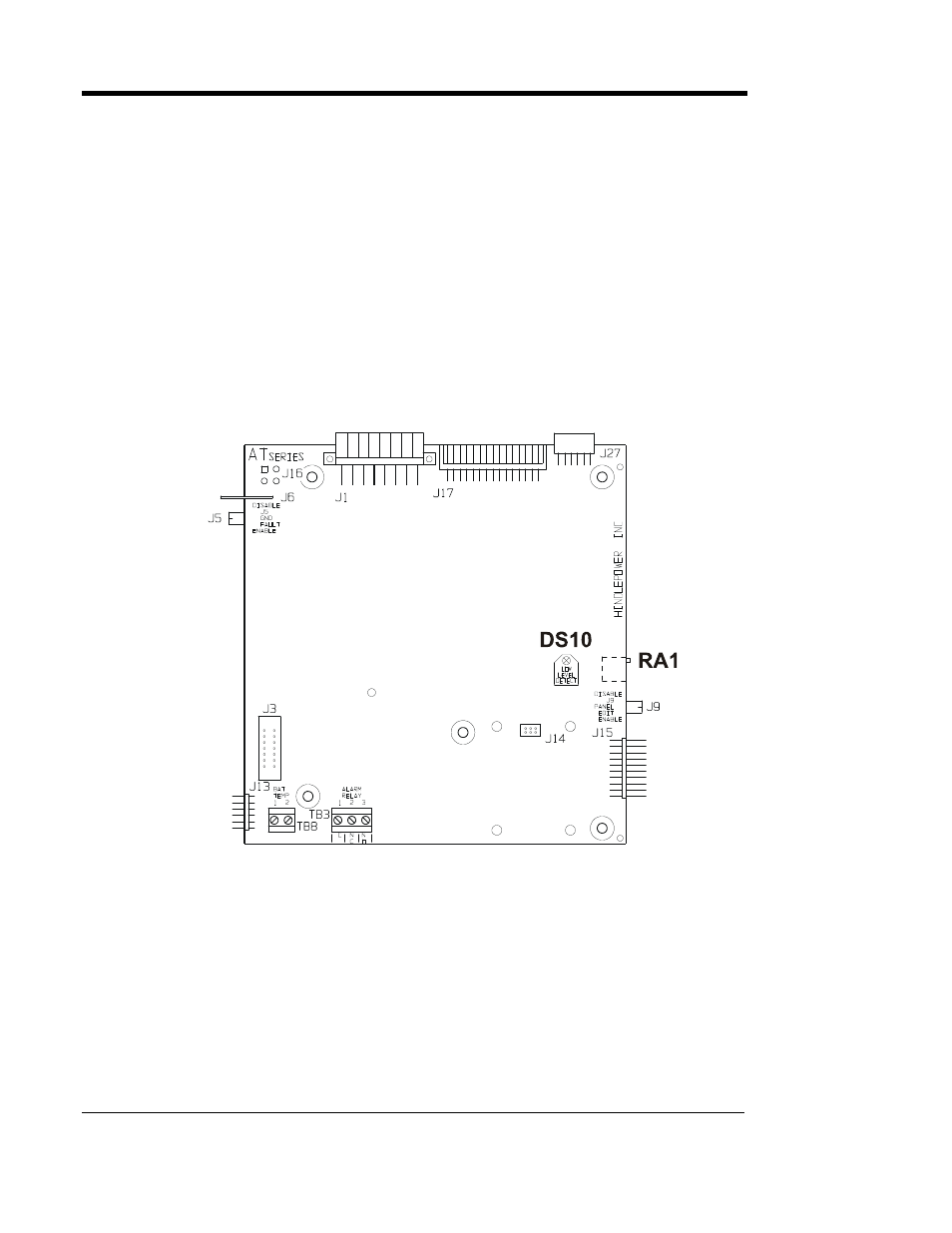
If you have a dc power supply, you can adjust the battery voltage that
triggers the alarm. On the back of the main control circuit board, find the
potentiometer RA1, as shown in the figure below.
Disconnect all ac and dc power sources from the AT10.1, and connect
your dc power supply to the dc output terminals of the charger (positive to
positive and negative to negative). Adjust the power supply to the voltage
at which you want to activate the alarm.
NOTE: You need at least 50% of the nominal output voltage to power the
AT10.1 control circuit board.
Adjust RA1 with a small jeweler's screwdriver clockwise until the alarm
just activates. A red LED indicator (DS10) next to RA1 indicates when
the alarm is active.
38