Installing the at10.1 – Exide Technologies Section 94.20 User Manual
Page 17
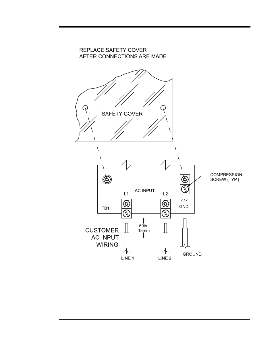
INSTALLING THE AT10.1
MAKING THE AC INPUT CONNECTIONS - GRAPHICS
NOTES
1. The drawing above does not show other components mounted to the I/O
panel. Be careful not to disconect any other component leads.
2. Always use a proper ground.
3. Use copper or aluminum conductors only.
4. On 120 Vac input, connect the neutral leg to the terminal L2.
13
See also other documents in the category Exide Technologies Power suppliers:
- GB3565 (4 pages)
- GB3696 (8 pages)
- GB3846 (4 pages)
- GB3902 (8 pages)
- GB3912 (2 pages)
- GB3914 (2 pages)
- GB3914S (2 pages)
- GB3979 (7 pages)
- GB4007 (4 pages)
- GB4013 (8 pages)
- GB4103 (4 pages)
- GB4109 (32 pages)
- GB4127 (31 pages)
- GB4128 (19 pages)
- GB4139 (6 pages)
- GB4145 (4 pages)
- GB4146 (8 pages)
- GB4158 (8 pages)
- SCR100 Charger (38 pages)
- SCRFLX Charger (38 pages)
- SPP PowrPak Series Industrial Battery Chargers (16 pages)
- V19CIL5200ULF (28 pages)
- V19CIL5200ULS (28 pages)
- JA5009-00 (68 pages)
- Section 92.30 (18 pages)
- Section 92.61 (32 pages)
- Section 92.80 (28 pages)
- Section 93.10 (20 pages)
- Section 93.10T (11 pages)
- Section 93.20 (68 pages)
- Section 93.30 (68 pages)
- Section 94.30 (100 pages)
- Section 94.40 (100 pages)
- Section 95.10 (18 pages)