Installing the at10.1, Schematic – Exide Technologies Section 94.20 User Manual
Page 20
INSTALLING THE AT10.1
1.9. WIRING THE AT10.1 FOR REMOTE SENSING
You can wire the AT10.1 to regulate the output voltage at the battery
terminals, instead of at the charger output terminals. Remote sensing does
the following:
1. Compensates for voltage drop in the dc wiring between the AT10.1 and the
battery.
2. Directly monitors the battery or dc bus voltage. The front panel meter
displays the actual voltage on the battery or dc bus.
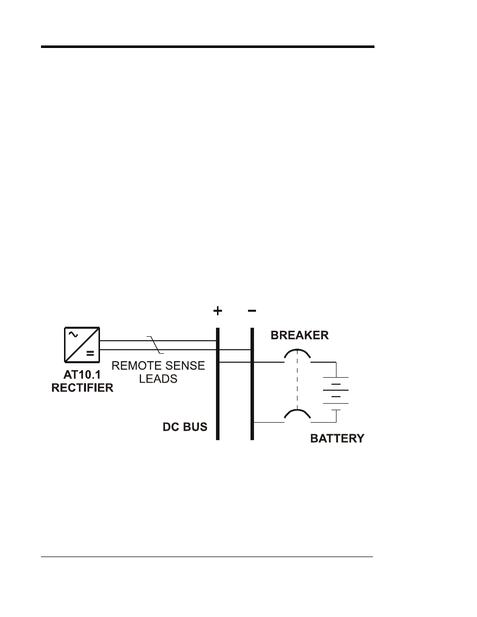
You wire the AT10.1 for remote sensing by installing twisted pair cabling
from the AT10.1 remote sense terminals to the battery terminals. The
AT10.1 control circuitry then measures the dc voltage at the battery
terminals, and controls the output of the charger to maintain the battery
voltage at the desired float or equalize voltage.
NOTE: If the remote sense wiring fails, the AT10.1 detects the fault,
and displays E 06 on the front panel meter. See Section 3.2 for details.
CAUTION: The AT10.1 cannot protect against short circuits in the
remote sense wiring. You should install a 1.0A fuse at the battery or dc
bus end of the remote sense cable.
SCHEMATIC
PROCEDURE
1. De-energize and lock out all ac and dc voltages within the AT10.1 enclosure.
Check with a voltmeter.
2. Remove safety shield.
3. Remove the two (2) dc output CU-AL compression lugs.
4. Move lugged end of R14 (with wire # 20) from TB1(-) to REM SENSE(-).
5. Move wire # 21 from TB1(+) to REM SENSE (+).
16