Tweco 201 ts Thermal Arc User Manual
Page 33
OPERATION
THERMAL ARC 161 STL, 201 TS
Manual 0-5203
4-3
Operation
only. Up Slope is not adjustable and activates automatically
in 4T mode when the TIG torch trigger is depressed. To
activate the Down Slope function in 4T mode while welding,
the TIG Torch Trigger Switch must be depressed and held
while welding which will ramp the Welding Current down
to zero over a defined period of time. The time period is
determined by the Down Slope Control Knob (F). At any time
while welding if the TIG Torch Trigger Switch is depressed
and released the arc will extinguish immediately.
D. Process Selection Switch-
161 STL
Switches between STICK (SMAW) and LIFT TIG (GTAW)
modes. Refer to Section 3.06 Setup for STICK (SMAW)
Welding and 3.07 Setup for TIG Welding.
201 TS
Switches between STICK (SMAW), LIFT TIG (GTAW) and HF
TIG (GTAW) modes. Refer to Section 3.06 Setup for STICK
(SMAW) Welding, 3.07 Setup for LIFT TIG (GTAW)Welding
and 3.08 Setup for HF TIG (GTAW)Welding.
E. Welding Current Control
The welding current is increased by turning the Weld Current
Control Knob clockwise or decreased by turning the Weld
Current Control Knob counterclockwise. The welding current
should be set according to the specific application. Refer
to application notes in this section for further information.
F. Arc Force/Down Slope Control
Arc Force is effective when in STICK (SMAW) Mode only. Arc
Force control provides an adjustable amount of Arc Force
(or “dig”) control. This feature can be particularly benefi-
cial in providing the operator the ability to compensate for
variability in joint fit-up in certain situations with particular
electrodes. In general increasing the Arc Force control to-
ward ‘10’ (maximum Arc Force) allows greater penetration
control to be achieved. Down Slope operates in TIG mode
only. It is used to set the time for weld current to ramp down.
Refer to Item C (Trigger Mode Selection Switch) for further
information regarding Downslope operation.
G. Gas Outlet
The Gas Outlet is a 5/8”-18 UNF female gas fitting and is
utilized for the connection of a suitable TIG Torch.
H. Post Gas Flow (weld current dependant)
Post Gas Flow is the time Gas flows after the arc has
extinguished. The gas flow time is proportional to weld
current. This is used to cool and reduce oxidization of
the Tungsten Electrode. For example if the Welding Cur-
rent is set to 10 amps the Post Gas Flow time will be
approximately 3 seconds. For a Welding Current set to
160 Amps the Post Gas Flow time will be approximately
10 seconds. The Post Gas Flow time cannot be adjusted
independently of the Welding Current.
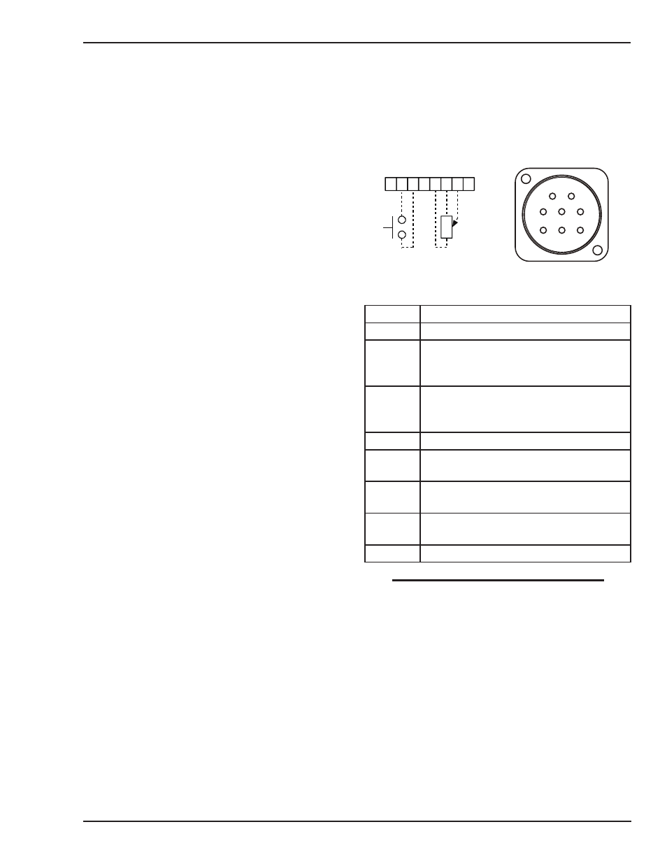
I. 8 Pin Remote Socket
The 8 pin remote socket is used to connect the TIG Torch
Trigger Switch to the welding Power Source. To make con-
nections, align keyway, insert plug, and rotate threaded
collar fully clockwise.
Art # A-09815_AB
1 2 3 4 5 6 7 8
5k Ohms
2
1
5
4
3
8
7
6
Front View of 8 Pin Socket
Plug Pin
Function
1
2
Torch Switch Input (24V) to energize weld
current. (connect pin 2&3 to turn on weld-
ing current)
3
Torch Switch Input (0V) to energize weld
current. (connect pin 2&3 to turn on weld-
ing current)
4
5
5k ohm (maximum) connection to 5k ohm
remote control potentiometer
6
Zero ohm (minimum) connection to 5k ohm
remote control potentiometer
7
Wiper arm connection to 5k ohm remote
control potentiometer
8
NOTE
Remote Welding Current Control is available through the
front panel of this unit. The remote will only go to the
maximum value that is set at the panel. If the panel is
set to 100 amps, the remote can't go above 100 amps
when fully adjusted.
J. ON/OFF Switch (located on rear panel not shown)
This switch controls the Mains Supply Voltage to the
Power Source.