Tweco 201 ts Thermal Arc User Manual
Page 21
INSTALLATION
THERMAL ARC 161 STL, 201 TS
Manual 0-5203
3-3 Installation
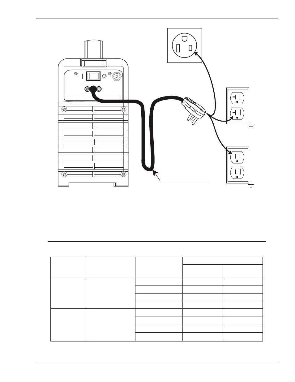
Welding Power Supply
Primary Power Cable
120
120
V,
V,
20A, 1Ø
15A, 1Ø
208-230V, 50A, 1Ø
The Adapters enable
connection to all these
power outlets
Art# A-09789
Figure 3-1: Electrical Input Connections
Input Power
Each unit incorporates an INRUSH circuit. When the MAIN CIRCUIT SWITCH is turned on, the inrush circuit provides
pre-charging for the input capacitors. A relay in the Power Control Assembly (PCA) will turn on after the input capacitors
have charged to operating voltage (after approximately 5 seconds)
NOTE
Damage to the PCA could occur if 253 VAC or higher is applied to the Primary Power Cable.
Model
Primary Supply Lead
Size (Factory Fitted)
Minimum Primary
Current Circuit Size
(Vin/Amps)
Current & Duty Cycle
LIFT TIG/ HF TIG
(GTAW)
STICK (SMAW)
Thermal Arc
161 STL
12 AWG (3.3mm²)
115V/30A
-
100A @ 45%
115V/30A
150A @ 35%
-
208-230V/25A
-
160A @ 30%
208-230V/15A
160A @ 30%
-
Thermal Arc
201 TS
12 AWG (3.3mm²)
115V/30A
-
100A @ 45%
115V/30A
150A @ 35%
-
208-230V/25A
-
200A @ 20%
208-230V/25A
200A @ 25%
-
Table 3-2: Primary Circuit Sizes to Achieve Maximum Current