Ultra-cut 100, Thermal dynamics, Key plug – Tweco 100 Ultra-Cut(March 2013) User Manual
Page 149
Manual 0-5132
A-17
APPENDIX
ULTRA-CUT 100
Art # A-06993_AD
6
6
7
7
8
8
9
9
10
10
A
B
C
D
E
F
POT HI (GCM1000)
POT WIPER (GCM1000)
POT LOW (GCM 1000)
PLASMA ENABLE
PRESS OK (GCM 1000)
PLASMA ENABLE
24VAC
24 VAC
R
E
T
+15V
/ AC
/ TEMP
/ STATUS
/ DC
/ GAS - COOLANT
- ARC V
- ARC V
AC24V-GCM
0V-A (24V ret)
AC120V-GCM
0V-B (120V ret)
AC120V-RAS
0V-RAS (120V ret)
DC 15V
DC 0V
NEG
ARC VO
LTS
PILOT (TIP) VOLTS
WORK
0V-A (24V ret)
AC24V-GCM
0V-B (120V ret)
AC120V-GCM
WORK
NEG ARC VOLTS
DWG No:
Sheet
of
Supersedes
Scale
Date:
Drawn:
References
Date
By
Revisions
Rev
PCB No:
Assy No:
Information Proprietary to THERMAL DYNAMICS CORPORATION.
Not For Release, Reproduction, or Distribution without Written Consent.
NOTE: UNLESS OTHERWISE SPECIFIED -
1. RESISTOR VALUES ARE EXPRESSED IN OHMS, 1/4W 5%.
2. CAPACITOR VALUES ARE EXPRESSED IN MICROFARADS (uF).
Chk:
App:
TITLE:
Last Modified:
Size
SCHEMATIC,
Thermal
Dynamics
AA
42X1209
Friday, September 25, 2009
2
2
Industrial Park #2
West Lebanon NH 03784
603-298-5711
100-Amp Power Supply 208-230/460V (Chopper)
Tuesday, October 03, 2006
08:11:44
Thermal Dynamics
D
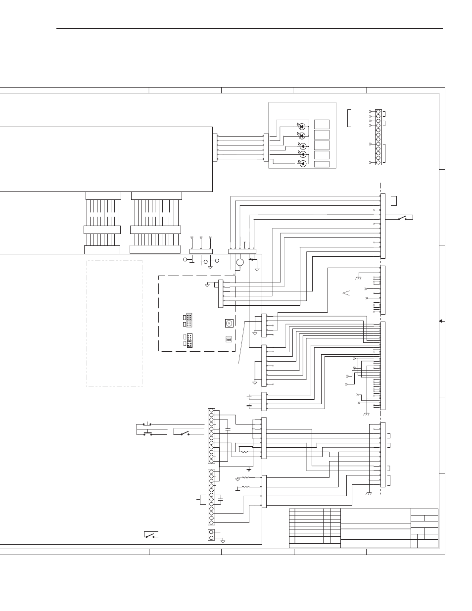
KEY PLUG
CN11 34 CKT
CN10 26 CKT
J36 34 CKT
J35 26 CKT
RIBBON CABLE
TEST SOCKET
RIBBON CABLE
TEST SOCKET
(E2)
(E2)
(E4)
(F4)
POWER SUPPLY
REAR PANEL
TB1
TB2
DIVIDED ARC V +
DIVIDED ARC V -
REMOTE ANALOG CURRENT CONTROL -
REMOTE ANALOG CURRENT CONTROL +
E-STOP -
E-STOP +
PILOT ON
OUTPUT
HOLD START -
HOLD START +
PREFLOW ON -
PREFLOW ON +
OK to MOVE -
OK to MOVE +
MOMENTARY START / STOP
START / STOP
STOP
START
+
-
JUMPER IN
REMOTE
HMI
PLASMA ENABLE
PCB6 DISPLAY
WK-5603
START / STOP
DIVIDED ARC VOLTS
REMOTE ANALOG
CURRENT CONTROL
OK TO MOVE
DAT
Signal - Basic ID
Used to identify
GCM 1000 present
RIBBON CABLE SIGNALS
/ = active low digital signal
CN10-J35 - 26 Ckt Ribbon Cable
2-Cut Demand
4-Pilot Demand
6-/ Start
7-/ Start2
9-/ Pilot Enable
10-/ HF Enable
12-/ Pump Enable
13-/ Fan Enable
15-/ DC Indicator
16-/ Over Temperature Indicator
18-/ Gas-Coolant OK Indicator
19-/ Status Lamp
CN11-J36 - 34 Ckt Ribbon Cable
1- Output Current Signal
3- / Arc Transferred (CSR)
4- / Pilot On
6- Coolant Flow (freq)
7- Coolant Temp (analog)
9- / Temp OK (Inverter/Chopper)
10- / Coolant Level OK
12- Missing Phase
13- / Ready to Operate
15- / Input Volts OK
16- / Inverter OCR
18- / PS ID "00*"
19- / PS ID "0*0"
20- / PS ID "*00"
21- E-Stop
22- E-Stop
29,31,33- 24 VAC Supply
30,32,34- 24 VAC Return
ECO-B402 DAT 2/26/07
AB
ECO-B448 DAT 4/13/07
INTERNAL TERMINAL
STRIP TB3
(Not in all units)
(E2)
(C9, sht 1)
(A9, sht 1)
UNDIVIDED ARC VOLTS
FOR HEIGHT CONTROLS
24 VAC @ 1A
120 VAC @ 100ma.
(A9, sht1)
(B9, sht1)
(C9, sht1)
AC
ECO-B646 GAC 10/31/07
* OK2
* OK2
* +10VDC @ 10 ma.(for CC pot high)
TB3
* REMOTE MARKING +
* REMOTE MARKING -
* Only in CCM w/
19X2634 I/O PCB.
Remote Marking
only for DFC 3000
(not isolated)
AD ECO-B1391
DAT
4-24-2009
** RS 485 / 422
on CPU board
19X2554 only.
Iso
Rx-
Tx+
Rx+
Tx-
Rx-
Tx+
Rx+
Tx-
KEY PLUG
JUMPER
for 2 WIRE
(RS485 only)
wire to A & B
4W
4W
2W
JUMPER
for 4 WIRE
uses
TX+, TX-
RX+, RX-
J14
J14
2W
SW14
SW14 - LINE
TERMINATION
normally on
(refer to manual)
5
9
8
7
6
1
2
3
4
SW10-ADDRESS
normally 0
(refer to
manual)
0
Signal & GND
Isolated from
Plasma Supply
RS 485 (2 wire)
uses Tx+ & Tx- only
(used for TSC 3000)
RS 422 (4 wire)
connect TX+ to RX+
of CNC, Tx- to Rx-
of CNC
Was 7 pin
changed to
14 pin in 2009
GND
GND
& CNC COMM
DAT
AE
ECO-B1535
9-25-09
100K
100K
PSR
PSR
7
7
GREEN
DC
GREEN
DC
7
7
4
4
9
9
8
8
8
8
J6
J6
1
5
8
9
9
GREEN
AC
GREEN
AC
9
9
E-STOP
E-STOP
J15-CNC
J15-CNC
1
2
3
4
5
6
7
8
9
10
11
12
13
14
3
3
8
8
100K
100K
K6-1
K6-1
10
10
1K
1K
10
10
2
2
1
1
11
11
11
11
K6
K6
3
3
J54-REMOTE HMI
J54-REMOTE HMI
1
2
3
4
5
6
7
8
9
10
11
12
13
14
2
2
7
7
12
12
J59-RAS
J59-RAS
1
2
3
4
5
6
7
8
9
10
11
12
13
14
12
12
TP11
TP11
2
2
12
12
2
2
4
4
OK2 *
OK2 *
CN23
CN23
1
2
3
4
5
6
RED
STATUS
RED
STATUS
J4
J4
1
3
5
7
YELLOW
TEMP
YELLOW
TEMP
1
1
3
3
TP1
TP1
1
1
6
6
11
11
1
1
J55-GCM
J55-GCM
1
2
3
4
5
6
7
8
9
10
11
12
13
14
15
16
17
18
19
20
21
22
23
24
25
26
27
28
29
30
31
32
33
34
35
36
37
4
4
J8
J8
1
2
3
4
J1
J1
1
2
3
4
5
6
7
8
9
5
5
CN24
CN24
1
2
3
4
5
6
TP12
TP12
5
5
5
5
GREEN
GAS
GREEN
GAS
J7
J7
1
2
3
4
5
6
7
8
9
10
10
6
6
J5
J5
1
2
3
4
5
J9
J9
1
2
3
4
5
6
J6 **
J6 **
1
2
3
4
5
6
6
6
GAS ON
GAS ON