Ultra-cut 400, 07 ground connections – Tweco 400 Ultra-Cut User Manual
Page 35
Manual No. 0-5164
3-9 INSTALLATION
ULTRA-CUT 400
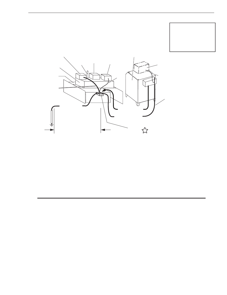
3.07 Ground Connections
0 - 10 ft (0 - 3 m) Ideal
20 ft (6 m) Maximum
1/0
Ground Cable
Power Supply
‘Star’
Ground
Earth Ground
Rod
1/0 Ground Cable
See
Manufacturer
CNC
Device
Torch
Cutting Table
Cutting Machine / Gantry
2/0 Work Cable
Remote Arc
Starter (RAS-1000)
Star Ground on Cutting Table
300Amp or more
Ultra-Cut
or
Auto-Cut O2
Note: The gas control module can
be mounted on top of the power
supply.
If it is, it should be grounded
directly to the power supply with
#4 AWG ground, (F).
This alternate location requires
grounding the power supply to the
‘Star’ ground with the 1/0 Ground
Cable (F1).
Gas Control Module
Primary location
#4 AWG
Ground
(F)
Customer supplied
1/0
Ground Cable
(F1)
Art # A-09538
A. Electromagnetic Interference (EMI)
Pilot arc starting generates a certain amount of electromagnetic interference (EMI), commonly called RF noise. This
RF noise may interfere with other electronic equipment such as CNC controllers, remote controls, height controllers,
etc. To minimize RF interference, follow these grounding procedures when installing mechanized systems:
B. Grounding
1. The preferred grounding arrangement is a single point or “Star” ground. The single point, usually on the cutting
table, is connected with 1/0 AWG (European 50 mm
2
) or larger wire to a good earth ground (measuring less
than 3 ohms; an ideal ground measures 1 ohm or less. Refer to paragraph ‘C’, Creating An Earth Ground. The
ground rod must be placed as close as possible to the cutting table, ideally less than 10 ft (3.0 m), but no more
than 20 ft (6.1 m) from the cutting table.
NOTE
All ground wires should be as short as possible. Long wires will have increased resistance to RF fre-
quencies. Smaller diameter wire has increased resistance to RF frequencies, so using a larger diameter
wire is better.
2. Grounding for components mounted on the cutting table (CNC controllers, height controllers, plasma remote
controls, etc.) should follow the manufacturer’s recommendations for wire size, type, and connection point loca-
tions.
For Thermal Dynamics components (except Remote Arc Starter and Gas Control Module) it is recommended
to use a minimum of 10 AWG (European 6 mm
2
) wire or flat copper braid with cross section equal to or greater
than 10 AWG connected to the cutting table frame. The Remote Arc Starter uses 1/0 earth ground wire and the
Gas Control Module should use minimum # 4 AWG wire. The connection point must be to clean bare metal;
rust and paint make poor connections. For all components, wires larger than the recommended minimum can
be used and may improve noise protection.