Ultra-cut 400, Connect input power and system ground cables – Tweco 400 Ultra-Cut User Manual
Page 33
Manual No. 0-5164
3-7 INSTALLATION
ULTRA-CUT 400
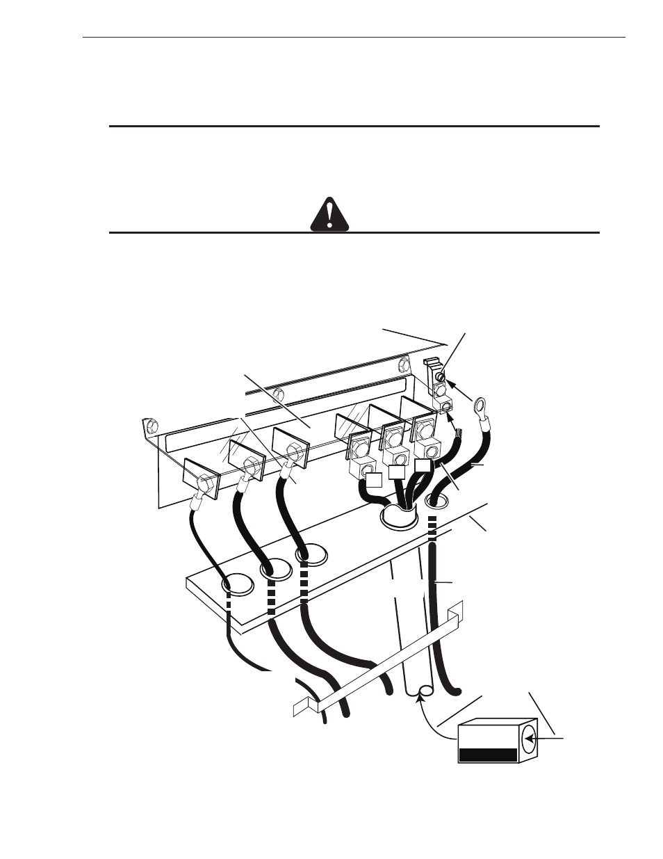
Connect Input Power and System Ground Cables
1. Carefully cut back the outer sheath on the primary input power cable to expose the individual wires. Cut back
the insulation on the individual wires. Route the cable upward through leads bracket at the bottom of the rear
panel, then through the connections cover support panel on the rear panel of the power supply.
NOTE
For CE versions the cable will need to be routed through the EMC filter box first. See following illustration.
2. Install stripped end of 3 phase wires into the terminal block L1, L2 and L3.
3. Connect the individual cables as shown. Connect the power cable ground cord to the ground terminal block.
CAUTION
The clear connections cover must remain in place.
4. If required pass a system ground cable (F1) through the last opening in the connections cover support panel
next to the input power cable. Connect the cable to the ground terminal block on the power supply rear panel.
Refer to the Ground Connections Section for full details and procedures on proper system grounding.
PILOT
WORK
TO
RCH
Input power cable
Ground Terminal Block
Connections Cover
Support Panel
System Ground Cable
Art # A-09834
to Remote Arc Starter
Connections Cover
Connection Panel
Leads Bracket
to Remote Arc Starter
AC INPUT
System Ground Cable
Input power cable ground
L1 L2
L3
L1
L2
L3
Input power cable
EMC Filter
CE units ONLY