Ultra-cut 400, 02 system layout – Tweco 400 Ultra-Cut User Manual
Page 28
INSTALLATION
3-2
Manual No. 0-5164
ULTRA-CUT 400
Coolant Capabilities
Cat. Number and Mixture
Mixture
Protects To
7-3580 ‘Extra-Cool™’
25 / 75
10° F / -12° C
7-3581 ‘Ultra-Cool™’
50 / 50
-27° F / -33° C
7-3582 ‘Extreme Cool™’
Concentrate*
-76° F / -60° C
* For mixing with D-I Cool™ 7-3583
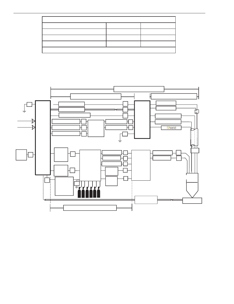
3.02 System Layout
Refer to section 3.05 for ground connections and ground cables.
CNC
Art # A-09537
Control
Cable
Fiber
Optic
Cable
Control
Cable
Gas Control
Module
Torch
Valve
Assembly
P
I
J
K
L
H
Q
R
S
Plasma Gas
Shield Gas
Plasma Gas
Shield Gas
Preflow Gas
Work
Torch
Positioning Tube
Water
Shield
G
T
Work Cable
175’ / 53.3 m Maximum Length
Primary power
Remote
Arc
Starter
Coolant Supply 10’
Coolant Return 10’
Control Cable
Pilot Return
Coolant Supply
Coolant Return
Ultra-Cut
Power
Supply
Shield
Negative Cable
Pilot Return #8
50’ / 15.25 m Maximum Length
Shield
A
B
E
C
D
125’ / 38.1 m Maximum Length
175’ / 53.3 m Maximum Length
F1
F1
HE 400
Heat
Exchanger
Control Cable
C
D
Y
Coolant Supply
Coolant Return
F
GroundCable
Only when
GCM is
mounted on
top of PS.
F1
- PAK 200i (160 pages)
- 211i Fabricator (96 pages)
- 15C Drag-Gun LT (32 pages)
- AirCut 15C (36 pages)
- TD-750 Cutting Systems (32 pages)
- TD-750 Cutting Systems (32 pages)
- 6000 Cutting System (36 pages)
- 100 Auto-Cut (104 pages)
- 100 Auto-Cut (148 pages)
- Auto-Cut 100 Torch Operation (20 pages)
- 200 Auto-Cut (136 pages)
- 300 Auto-Cut (164 pages)
- C-20A CUTSKILL (32 pages)
- C-35A CUTSKILL (36 pages)
- C-70A CUTSKILL (36 pages)
- 15XC CE Merlin PAK (134 pages)
- 6000 CE Merlin (78 pages)
- Merlin 6000 Plasma Cutting CE Slave Power Supply (48 pages)
- 6000GST Merlin Plasma Cutting CE Slave Power Supply (78 pages)
- 150XL CE PAK Master Without Latch Circuit (54 pages)
- CutMaster 101 (62 pages)
- CutMaster 101 with SL100SV (172 pages)
- CutMaster 10mm (66 pages)
- CutMaster 10mm-12mm (44 pages)
- CutMaster 12mm-20mm-25mm (80 pages)
- CutMaster 12mm (76 pages)
- 151 CutMaster (60 pages)
- 151 with SL100SV (172 pages)
- 152 CutMaster (84 pages)
- 15mm Cutmaster (44 pages)
- 20mm Cutmaster (80 pages)
- 25mm Cutmaster (80 pages)
- CutMaster 35mm 40mm (80 pages)
- CutMaster 35mm (84 pages)
- 38 CutMaster (54 pages)
- 38 CutMaster (51 pages)
- 39 CutMaster (68 pages)
- 42 CutMaster Operating Manual (35 pages)
- 42 CutMaster Service Manual (78 pages)
- 50 CutMaster (44 pages)
- 51 CutMaster (60 pages)
- 51 with SL100SV CutMaster (172 pages)
- 82 PlazMaster (80 pages)
- 102 Cutmaster (80 pages)
- 81 CutMaster (63 pages)