Ultra-cut 400 – Tweco 400 Ultra-Cut User Manual
Page 32
INSTALLATION
3-6
Manual No. 0-5164
ULTRA-CUT 400
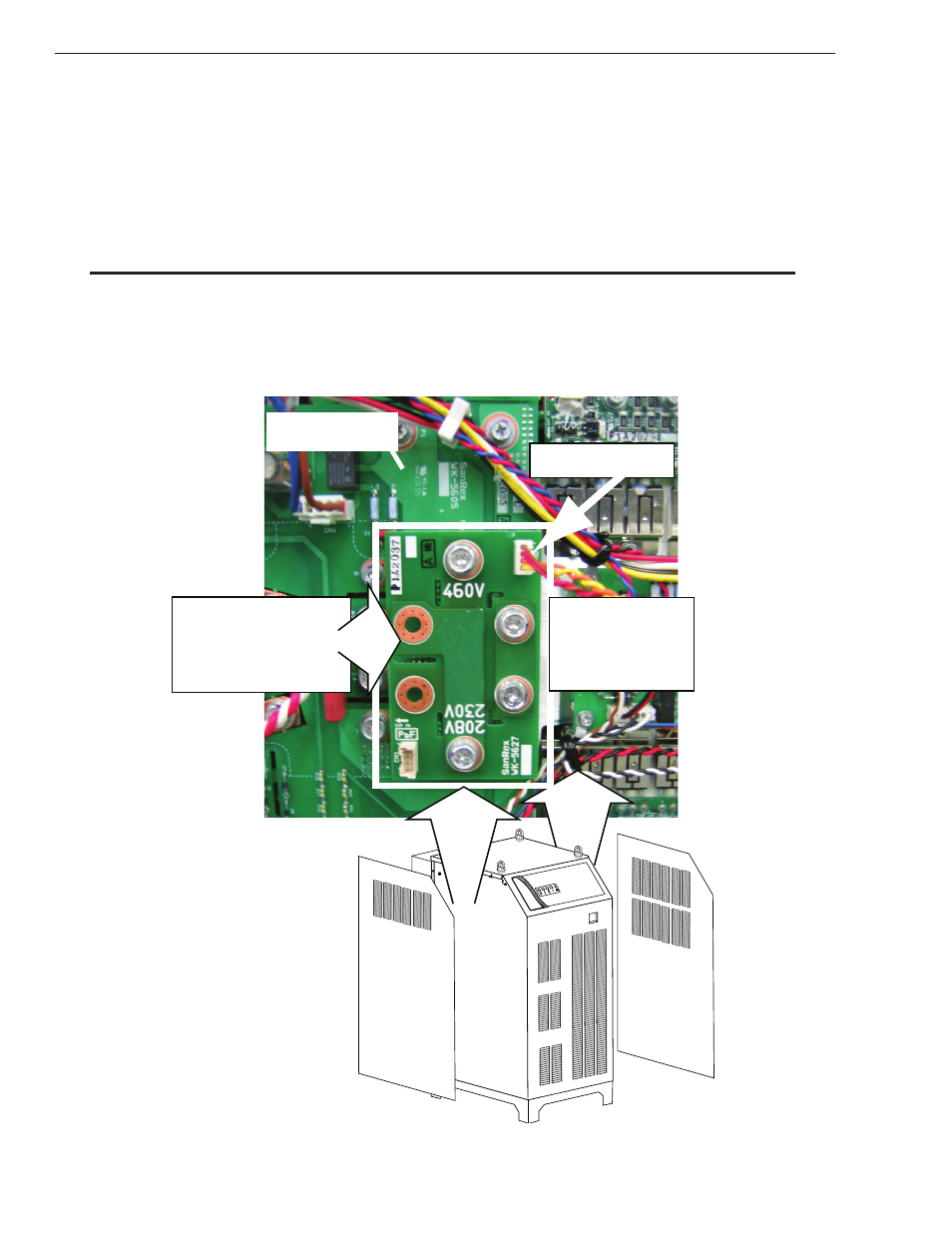
Check / Adjust Input Voltage Configuration for 208/230 and 460V Systems
1. The 208/230 and 460 V power supply includes a voltage configuration board which must be positioned to match
the primary input voltage. Remove the power supply left and right side panel and locate the voltage configura-
tion board. The input voltage configuration is shown at the top of the board for three on the left side and on the
bottom for the single one on the right side. See NOTE.
2. If necessary, disconnect the jumper at the top right corner of the board, remove the board and reinstall it with
the correct input voltage shown at the top of the board.
3. Reconnect the jumper. Reinstall the power supply side panel.
NOTE:
There are 4 inverters in the power supply. 3 on one side and 1* on the other. The single inverter will be
installed upside down (opposite) of the other 3 so the 460V will be on the bottom when the other 3 will
be on top as shown below.
1. Unplug connector
2. Remove bolts.
3. Invert board.
4. Re-install board.
5. Plug in connector.
208/230V / 460V
Input Voltage Board
(Shown in 460V Position)
Inverter Module
Art # A-09452
3
1*