Tweco PCM - 102 Machine Torch User Manual
Page 41
Manual 0-2818
5-9
SERVICE
2. Cut the Torch Switch leads between the butt
splices and the torch leads, and as close as pos-
sible to the splices.
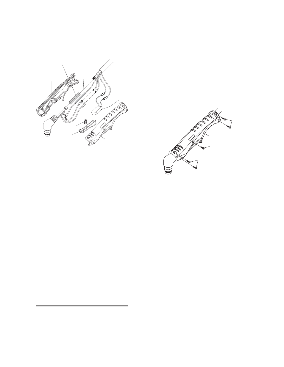
Handle Shell
Handle Shell
Spring
Trigger
Torch
Switch
Negative / Plasma Lead
Insulation Sleeving
Pilot Lead
Insulation
Sleeving
A-03544
Figure 5-11 Hand Torch Assembly
3. Remove the defective Torch Switch from the
handle.
D. Reassembling Hand Torch Control Switch
Assembly
1. Strip back the insulation from the Torch Switch
leads approximately 3/16". Install heat-shrink
insulation on the Torch Switch leads. Crimp butt
splices onto the two Torch Switch leads and onto
the switch leads in the Torch Leads assembly.
Slide the sheat-shrink insulator over the butt
splices. Use a heat gun to shrink the heat-shrink
insulation into position on the butt splices.
2. Position Torch Head and Torch Control Switch in
handle, making sure all connectors and leads do
not extend beyond the edge of the handle.
3. Position Pilot Lead under the Negative / Plasma
Lead.
4. Position the Pilot Lead so that the screw will not
penetrate the Insulation Sleeving when the handle
halves are reassembled.
NOTE
For safety reasons, it is critical that the sleeving
not be used if it is damaged during reassembly.
Replace sleeving if damaged.
5. Replace the handle and secure with five screws
as follows:
a. Insert the two screws at the Torch Head end
of the Handle and torque to 15 in-lbs.
b. Insert the two screws at the Torch Lead end of
the Handle and torque to 15 in-lbs.
c. Insert the center screw and torque to 15 in-lbs.
d. Check the Torch Trigger for proper operation.
It should move freely and not bind. If the trig-
ger binds, loosen the center screw only until
the Trigger moves freely.
A-02824
Handle Half
#1
#2
#3
Install Screws In
Sequence Shown
Figure 5-12 Torch Handle Screw Installation