Workpiece power supply + _ c b a – Tweco PCM - 102 Machine Torch User Manual
Page 17
Manual 0-2818
2-3
INTRODUCTION
;;
;;
;;
;
;
;
;
;
;;
;;
A-00002
Workpiece
Power
Supply
+
_
C
B
A
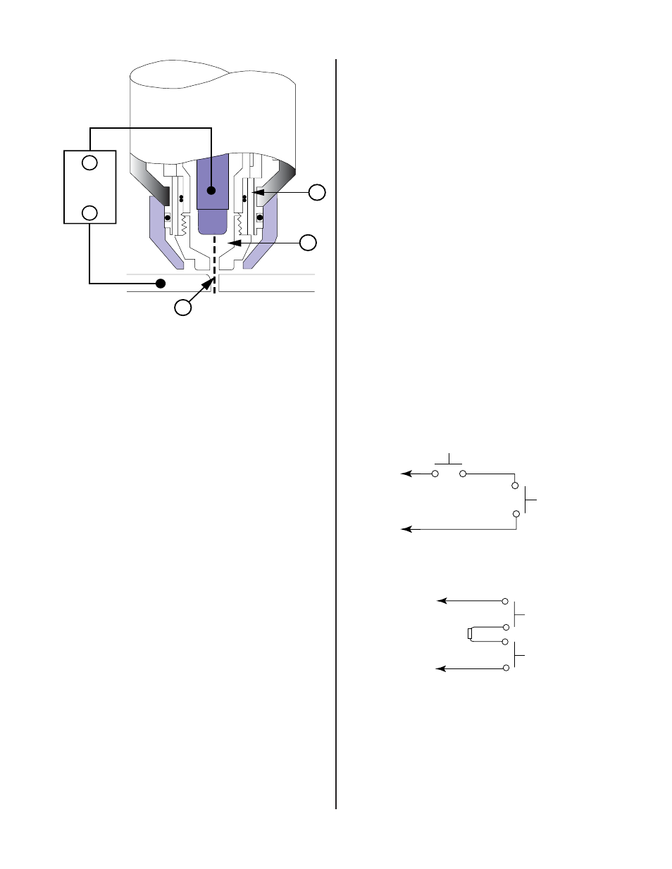
Figure 2-2 Typical Torch Head Detail
By forcing the plasma gas and electric arc through a small
orifice, the torch delivers a high concentration of heat to a
small area. The stiff, constricted plasma arc is shown in
Zone C (Figure 2-2). Direct current (DC) straight polarity is
used for plasma cutting, as shown in the illustration.
Zone A (Figure 2-2) is used as a secondary gas that cools
the torch. This gas assists the high velocity plasma gas in
blowing the molten metal out of the cut allowing for a fast,
slag-free cut.
B. Gas Distribution
The single gas used is internally split into plasma and sec-
ondary gases.
The plasma gas flows into the torch through the negative
lead, through the gas distributor, around the electrode,
and out through the tip orifice.
The secondary gas flows down around the outside of the
torch gas distributor, and out between the tip and shield
cup around the plasma arc.
C. Pilot Arc
When the torch is started a pilot arc is established be-
tween the electrode and cutting tip. This pilot arc creates
a path for the main arc to transfer to the work.
D. Capacitive Discharge
Because direct current (DC) alone is not sufficient to strike
and maintain the pilot arc, capacitive discharge is also used.
The high voltage jumps between the tip and electrode with
the DC following.
E. Main Cutting Arc
DC power is also used for the main cutting arc. The nega-
tive output is connected to the torch electrode through the
torch lead. The positive output is connected to the work-
piece via the work cable and to the torch through a pilot
wire.
F. Interlocks
One pressure switch acts as an interlock for the gas sup-
ply. If supply pressure falls below minimum requirements
the pressure switch will open, shutting off the DC power,
and the GAS indicator will go off. When adequate gas
supply pressure is available the pressure switch will close,
allowing power to be resumed for cutting.
G. Parts-In-Place (PIP)
The torch head has built-in contacts called Parts-In-Place
(PIP). These two contacts are made through the canted
coiled spring inside the shield cup when it is installed. The
torch will fail to operate if these contacts are not made.
A-00458
Torch Switch
PIP Pin
PIP Pin
Shield Cup
To Control
Cable Wiring
Figure 2-3A Parts-In-Place (PIP) Diagram - Machine
Torch
A-03761
Torch Trigger
PIP Switch
Shield Cup
To Control
Cable Wiring
Torch Switch
Figure 2-3B Parts-In-Place (PIP) Diagram - Hand
Torch