Tweco PCM - 102 Machine Torch User Manual
Page 22
INSTALLATION
3-4
Manual 0-2818
3. Connect the torch Negative / Plasma Lead to the bulk-
head connection inside the Power Supply.
4. Connect the Control (PIP) Circuit Connectors to the
mating connectors on the Adapter supplied on the
Power Supply (see Warning).
WARNING
The Adapter supplied with the Power Supply has
two additional Shield Connectors that are used for
Shielded Systems only. These two connectors are
not used and need to be taped out of the way to
prevent contacting the Negative & Plasma or Pi-
lot Leads.
5. Remove the top nut and washer from the Pilot
Stud.
6. Place the lug on the Pilot Control Wire onto the
stud and secure with the nut and washer removed
in the above Step.
7. Tighten the Through-hole Protector onto the Torch
Leads.
8. Check the torch for proper parts assembly.
CAUTION
The torch parts must correspond with the type of
operation. Refer to Section 4.04, Torch Parts Se-
lection.
C. Machine Systems (Shielded Leads)
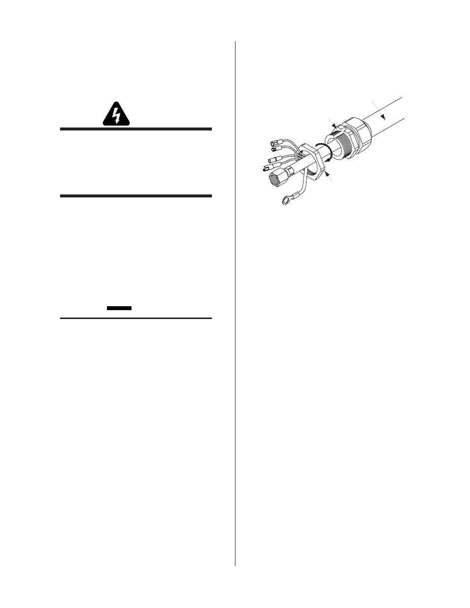
1. Remove the Through-hole Protector Nut from the
Through-hole Protector.
Through - Hole
Protector Nut
Through - Hole
Protector
Torch Leads
Assembly
Art # A-03849
Figure 3-6 Through-hole Protector Nut Removal
2. The Adapter supplied with the Power Supply must be
installed per the following:
a. Inside the Power Supply Bulkhead area, route the
connector on the free end of the Adapter through
the Through-hole Protector Nut.
b. Continue routing the connector out the hole in the
front of the Power Supply.
c. Feed the end of the torch lead and the Through-
hole Protector into the hole in the unit while rout-
ing the single black wire into the notch of the
Through-hole Protector.
d. Tighten the Through-hole Protector Nut to secure
the Through-hole Protector to the Power Supply.