03 sequence of operation, 03 sequence of operation -3 – Tweco 150XL CE PAK Master Without Latch Circuit User Manual
Page 29
Manual 0-2727
4-3
OPERATION
2.
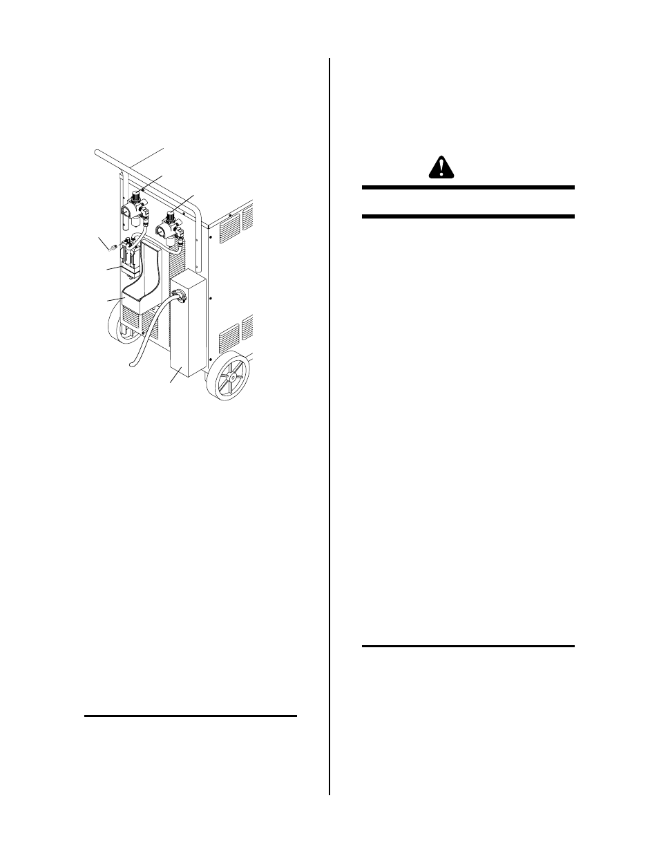
Plasma Gas Pressure Regulator/Filter Assembly
Pressure Regulator to adjust the plasma input gas
pressure to the Power Supply. The Pressure Regu-
lator has a built-in air line filter.
A-02297
5
2
3
4
1
6
Figure 4-4 Rear Panel
3.
Secondary Gas Pressure Regulator/Filter Assem-
bly
Pressure Regulator to adjust the secondary input
gas pressure to the Power Supply. The Pressure
Regulator has a built-in air line filter.
4.
Coolant Reservoir
The coolant reservoir supplies the system with
coolant to cool the torch and torch parts during
operation. The maximum capacity of the reser-
voir is two gallons of coolant.
Inside the reservoir, in the filler hole, is a basket
and deionizer bag. The bag removes charged par-
ticles from the coolant after it is returned to the
reservoir and prevents the coolant from becom-
ing conductive. If the coolant becomes conduc-
tive it must be replaced (see NOTE).
NOTE
Refer to Section 5.02, General Maintenance, sub-
sections 'E' and 'F' for procedures on checking and
replacing coolant.
5.
Gas Input
Input connections for plasma and secondary gases.
Acceptable gases are as follows:
Plasma Gases - Air, Nitrogen, Argon Hydrogen
Secondary Gases - Air, Nitrogen, Carbon Dioxide
WARNING
This unit not to be used with oxygen (O
2
).
6.
Two Stage Air Line Filter
Two Stage Air Line Filter Assembly will remove
moisture and contaminants from the air stream
when using compressed air. The filter is capable
of filtering to at least 5 microns.
4.03 Sequence of Operation
The following is a typical sequence of operation for this
cutting system. Refer to Appendix 2 for a block diagram.
1.
Close main power source disconnect.
a. AC power is available at the Power Supply.
2.
Place RUN/SET switch to RUN mode.
3.
Place the ON/OFF power switch on the front panel
of the Power Supply to ON.
a. Fan turns ON.
b. Coolant Pump turns ON.
c. AC Power indicator LED blinks ON and OFF
for eight seconds then stays ON.
d. Start-up pre-purge of gas.
4.
Place RUN/SET switch to SET mode.
a. Gas Solenoid opens and gas flows to set pres-
sure.
b. GAS indicator turns ON.
NOTE
GAS indicator will not come ON if the gas pres-
sure is set below 40 psi (2.8 bar) at the Regulator/
Filter Assembly or if coolant flow switch is not sat-
isfied.
5.
Place RUN/SET switch to RUN mode.
a. Gas flow stops.
b. GAS indicator turns OFF.