08 ground connections for mechanized applications – Tweco 150XL CE PAK Master Without Latch Circuit User Manual
Page 23
Manual 0-2727
3-7
INSTALLATION PROCEDURES
Connect the CNC Control Cable and Torch Leads to the
Power Supply using the following procedure:
1.
Open the Access Panel to gain access to the Torch
Bulkhead Panel.
2.
Feed the connector on the end of the CNC Control
Cable through the rubber boot on the front panel
of the Power Supply (see NOTE).
NOTE
Feed the Control Cable through the rubber boot first
as there will not be enough space inside the rubber
boot for the connector if the Coolant and Gas Leads
have been fed through the rubber boot first.
3.
Connect the CNC Control Cable connector to the
Control Cable connector on the Torch Bulkhead
Panel.
4.
Feed the end of the Torch Leads through the rub-
ber boot.
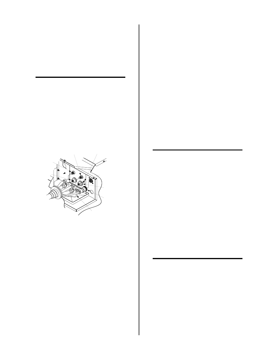
A-02113
Secondary
Gas
Plasma (+)
Gas
Control Cable
Connector
Coolant
Return
Coolant
Supply (-)
CNC Control
Cable
Torch Leads
Shield Stud
Shield Wire
With Ring Lug
Figure 3-9 Shielded Machine Torch Connections
5.
Connect the Torch Leads Shield Wire per the fol-
lowing procedure:
a. Remove one nut and star washer from the torch
leads shield stud on the Torch Bulkhead Panel.
b. Place the ring lug from the Torch Leads Shield
Wire over the shield stud.
c. Secure the wire with the nut and star washer.
6.
Connect torch coolant and gas leads to connectors
on the Torch Bulkhead Panel.
7.
Close the Access Panel and turn the two latching
screws.
8.
Check the torch for proper parts assembly.
9.
Connect the other end of the CNC Control Cable
to the desired equipment.
3.08 Ground Connections For
Mechanized Applications
A. Electromagnetic Interference (EMI)
Pilot arc initiation generates a certain amount of electro-
magnetic interference (EMI), commonly called RF noise.
This RF noise may interfere with other electronic equip-
ment such as CNC controllers, remote controls, height
controllers, etc. To minimize RF interference, follow these
grounding procedures when installing mechanized sys-
tems:
B. Grounding
1. The preferred grounding arrangement is a single point
or “Star” ground. The single point, usually on the cut-
ting table, is connected with 1/0 (42 mm
2
) or larger
wire to a good earth ground (refer to paragraph ‘C’,
Creating An Earth Ground). The ground rod must be
placed as close as possible to the cutting table. Ideally
less than 10 ft (3.0 m), but no more than 20 ft (6.1 m).
NOTE
All ground wires should be as short as possible.
Wires of long length will have increased resistance
to RF frequencies. Smaller diameter wire has in-
creased resistance to RF frequencies, so using a
larger diameter wire is better.
2. Components that are mounted on the cutting machine;
CNC controller, plasma remote controls, height con-
trollers, remote arc starters, etc., should be grounded
to the cutting machine frame (chassis) with at least a
12 AWG (4 mm
2
) wire. Flat copper braid works even
better.
3. The cutting machine frame is then connected to the
“Star” point using AWG 6 (13.3 mm
2
) or larger wire.
4. The plasma power supply work cable (see NOTE) is
connected to the cutting table at the single point “Star”
ground.
NOTE
Do Not connect the work cable directly to the
ground rod.
5. Make sure work cable and ground cables are prop-
erly connected. The work cable must have a solid
connection to the cutting table. The work and ground
connections must be free from rust, dirt, grease, oil
and paint. If necessary grind or sand down to bare
metal. Use lock washers to keep the connections tight.
Using electrical joint compound to prevent corrosion
is also recommended.