Section 4: operation, 01 introduction, 02 operating controls – Tweco 150XL CE PAK Master Without Latch Circuit User Manual
Page 27: Section 4, Operation -1, 01 introduction -1 4.02 operating controls -1, A. front and access panel, B. control panel
Manual 0-2727
4-1
OPERATION
SECTION 4:
OPERATION
4.01 Introduction
This section provides a description of the CE Power Sup-
ply operating controls and procedures. Identification of
the Front and Rear Panel components is followed by op-
erating procedures.
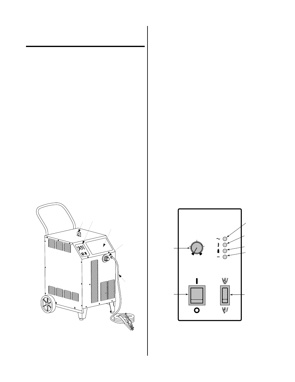
4.02 Operating Controls
This subsection provides specific functional descriptions
of the Power Supply operating controls and indicators.
A. Front and Access Panel
1.
Control Panel
All operator controls, except gas pressure adjust-
ment, are located on this panel and include:
• Power ON/OFF and RUN/SET switches
• CURRENT control
• LED indicators for AC Power, TEMP, GAS/
Coolant, and DC.
A-02079
1
2
3
4
5
Figure 4-1 Front and Access Panels
2.
Access Panel
A panel to gain access to the bulkhead area con-
taining the torch connections.
3.
Torch Leads Input
Rubber Boot and hole in the front panel to feed
the torch leads through to the internal bulkhead
connections.
4.
Work Cable and Clamp
Work cable with clamp (factory installed).
5.
Lifting Eye
Used to lift the Power Supply with cable and hook.
B. Control Panel
1.
Current Control
Adjustment to set the desired output current be-
tween 30-120 amps. For drag cutting applications
set the control between 30 - 35 amps. The unit has
an automatic fold-back circuit that limits current
to 35 amps during drag cutting.
2.
ON/OFF Power Switch
ON position supplies AC power to activate all sys-
tem control circuits. OFF position deactivates con-
trol circuits.
SET
RUN
RUN
ON
ON
OFF
OFF
TEMP
TEMP
AC
GAS
GAS
DC
DC
A
120
120
30
30
75
75
50
50
100
100
CURRENT
CURRENT
1
2
3
4
5
6
7
A-02078
Figure 4-2 Control Panel