Tweco 150XL CE PAK Master Without Latch Circuit User Manual
Page 28
OPERATION
4-2
Manual 0-2727
3.
RUN/SET Switch
RUN position is used for torch operation. SET po-
sition used for setting gas pressure and purging
lines.
4.
AC Power Indicator
Once ON/OFF power switch is set to ON, green
LED indicator will blink ON then OFF for approxi-
mately eight seconds and then stay ON. Indicates
operating power is present in the unit.
5.
TEMP Indicator
Normally OFF. Yellow LED indicator will come
ON when the internal temperature sensors detect
temperatures above normal limits. The unit
should be allowed to cool before continuing op-
eration.
6.
GAS/Coolant Flow OK Indicator
This LED is both a gas pressure and coolant flow
indicator.
A green LED indicator ON means the input gas
pressure is set to 40 psi (2.8 bar) or higher, and
there is adequate coolant flow of greater than 0.5
gpm
The Indicator will be OFF when the pressure falls
below 40 psi (2.8 bar) or there is not enough cool-
ant flow (less than 0.5 gpm) caused by damaged
hose(s), clogged filter(s), etc.
7.
DC Indicator
Green LED indicator will come ON while the torch
switch is pressed.
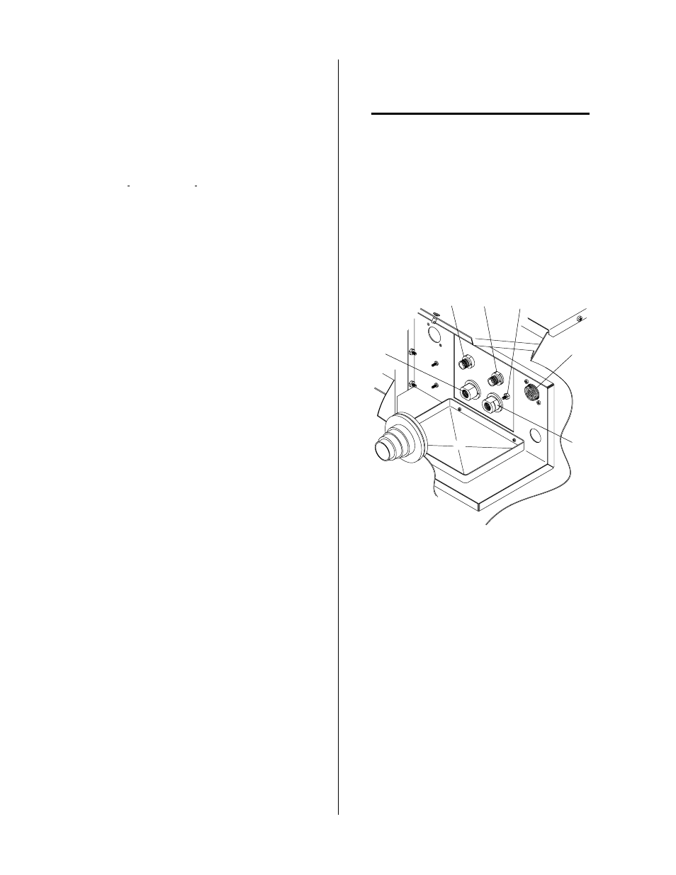
C. Torch Panel Bulkhead
The Torch Panel Bulkhead is located under the Access
Panel.
1.
Plasma (+) Gas Lead Connection
Left-hand thread fitting to connect the torch
plasma lead to the unit.
2.
Secondary Gas Lead Connection
Fitting to connect the torch secondary lead to the
unit.
3.
Coolant Supply (-) Lead Connection
Fitting to connect the torch coolant supply lead to
the unit.
4.
Coolant Return Lead Connection
Left-hand thread fitting to connect the torch cool-
ant return lead to the unit.
5.
Torch Lead Shield Stud (see NOTE)
Stud used to secure the torch lead shield ring lug.
NOTE
Used with Shielded Torch Leads only.
6.
Control Cable Connector
Connector used to interface the Torch Control
Cable to the unit. In Hand Torch applications in-
terfaces the Torch Switch to the unit. In Machine
Torch applications interfaces either Remote Hand
Pendant Control Cable (unshielded Torch Leads)
or CNC Control Cable (shielded Torch Leads).
A-02881
2
1
3
4
5
6
Figure 4-3 Torch Bulkhead Panel
D. Rear Panel
1.
Primary Power EMI Input Filter, Cable and Strain
Relief
The factory installed EMI Input Filter Assembly
is mounted to the rear panel of the power supply.
A strain relief is supplied to secure the shielded
primary input AC power cable to the EMI Input
Filter Assembly. The input cable is routed through
the strain relief and is connected to input termi-
nals of an input filter. The shielded input power
cable requires two ground connections outside of
the Power Supply:
• Power ground for the cable
• Shielded cable cover ground