Tweco 150XL CE PAK Master Without Latch Circuit User Manual
Page 22
INSTALLATION PROCEDURES
3-6
Manual 0-2727
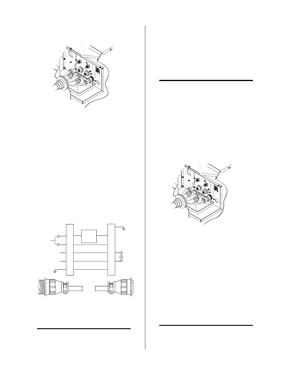
A-02949
Secondary
Gas
Plasma (+)
Gas
Control Cable
Connector
Coolant
Return
Coolant
Supply (-)
Control
Cable
Figure 3-6 Hand Torch Leads Connections
3.
Connect torch coolant and gas leads to connectors
on the Torch Bulkhead Panel.
4.
Close the access panel and turn the two latching
screws.
5.
Check the torch for proper parts assembly.
B. Machine Systems (Unshielded Leads)
Systems ordered with Unshielded Machine Torch will
include a Remote Hand Pendant. The Remote Hand Pen-
dant allows the operator to start the cutting operation
from a remote location.
2
3
4
12
14
13
Torch Control
Cable Connector
Remote Pendant/CNC
Cable Connector
PIP
Circuit
Control
OK-To-Move
3
4
12
14
13
A-01366
Figure 3-7 Remote Pendant Connector Diagram
NOTE
Equipment ordered as a System will have the Con-
trol Cable and Torch Leads factory connected to the
Power Supply.
Connect the Remote Hand Pendant and Torch Leads to
the Power Supply using the following procedure:
1.
Open the Access Panel to gain access to the Torch
Bulkhead Panel.
2.
Feed the connector on the end of the Remote Hand
Pendant Control Cable through the rubber boot
on the front panel of the Power Supply (see NOTE).
NOTE
Feed the Control Cable through the rubber boot first
as there will not be enough space inside the rubber
boot for the connector if the Coolant and Gas Leads
have been fed through the rubber boot first.
3.
Connect the Remote Hand Pendant Control Cable
connector to the Control Cable connector on the
Torch Bulkhead Panel.
4.
Feed the end of the Torch Leads through the rub-
ber boot.
A-02950
Secondary
Gas
Plasma (+)
Gas
Remote Hand
Pendant Control
Cable
Coolant
Return
Coolant
Supply (-)
Control Cable
Connector
Figure 3-8 Unshielded Machine Torch Connections
5.
Connect torch coolant and gas leads to connectors
on the Torch Bulkhead Panel.
6.
Close the Access Panel and turn the two latching
screws.
7.
Check the torch for proper parts assembly.
C. Machine Systems (Shielded Leads)
Systems ordered with Shielded Machine Torch will in-
clude a Computer Control (CNC) Control Cable. The
CNC Control Cable allows the Power Supply to interface
with a computer or other control device.
NOTE
Refer to Appendix 5 for CNC Control Cable Inter-
face Signal Diagram.