Tweco 6000 CE Merlin User Manual
Page 35
Manual 0-2601
3-17
INSTALLATION PROCEDURES
Master and Slave Power Supply pilot resistors are initially set
at the factory and may need to be adjusted to the customer's
input power (see Notes).
NOTES
The instructions in this Sub-Section apply to the
Master Power Supply only.
To adjust the Slave Power Supply pilot resistor,
refer to the Manual supplied with the Slave Power
Supply.
WARNING
Disconnect primary power at the source before as-
sembling or disassembling power supply, torch
parts, or torch and leads assemblies.
The pilot current consists of two parts:
1) Minimum or “background” level
2) Pulse or peak level
The background level has to be high enough that the pi-
lot will not sputter or go out, but not too high to cause
excessive wear of the torch consumables. Adding pulses
of current on top of the background current allows greater
arc transfer distance without increasing the torch part
wear. The amount of pilot current is determined by the
value of the pilot resistors and the open circuit voltage
which varies with the input line voltage. Both the Mas-
ter and the Slave Power Supplies should be adjusted the
same. Wire #99 tap sets the background level and wire
#150 tap sets the pulse level. Set the pilot background and
pulse levels as follows:
1. Remove the left and right side panels of the Master
Power Supply.
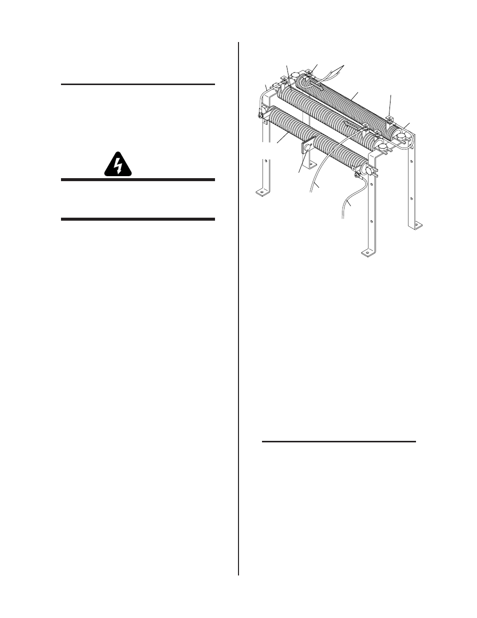
2. Locate and identify the pilot resistors (R16, R21 and
R22) which are on a bracket in front of the fan.
Wire
#96A
Pilot Resistor
R16
Clamp
Clamp
A-01853
Wire
#150
Pilot Resistor
R21
Pilot Resistor
R22
Wire
#74
Wire #99
Wire
#96
Temp
Switch
Figure 4-4 Location Of Pilot Resistors (Viewed From
The Front Of Power Supply)
3. Check the busbar configuration on the input terminal
board to determine which range the power transformer
is set for.
4. Measure the level of the AC line voltage being sup-
plied to the Power Supply.
5. To determine the recommended pilot resistor setting
use the following table as follows:
a. Find the voltage that is nearest what was measured
above.
b. Note the ohms value for the voltage. Example: If
the measured voltage is 360, then the pilot resistor
value is 6 ohms.
NOTE
Voltages that are from 410 to 420V require values
from 8.5 or 9 to 4.5 ohms. If the voltage is near one
of these points it is best to set for the lower ohms
value.