12 external cable connections, A. optional rc 6010 remote control – Tweco 6000 CE Merlin User Manual
Page 31
Manual 0-2601
3-13
INSTALLATION PROCEDURES
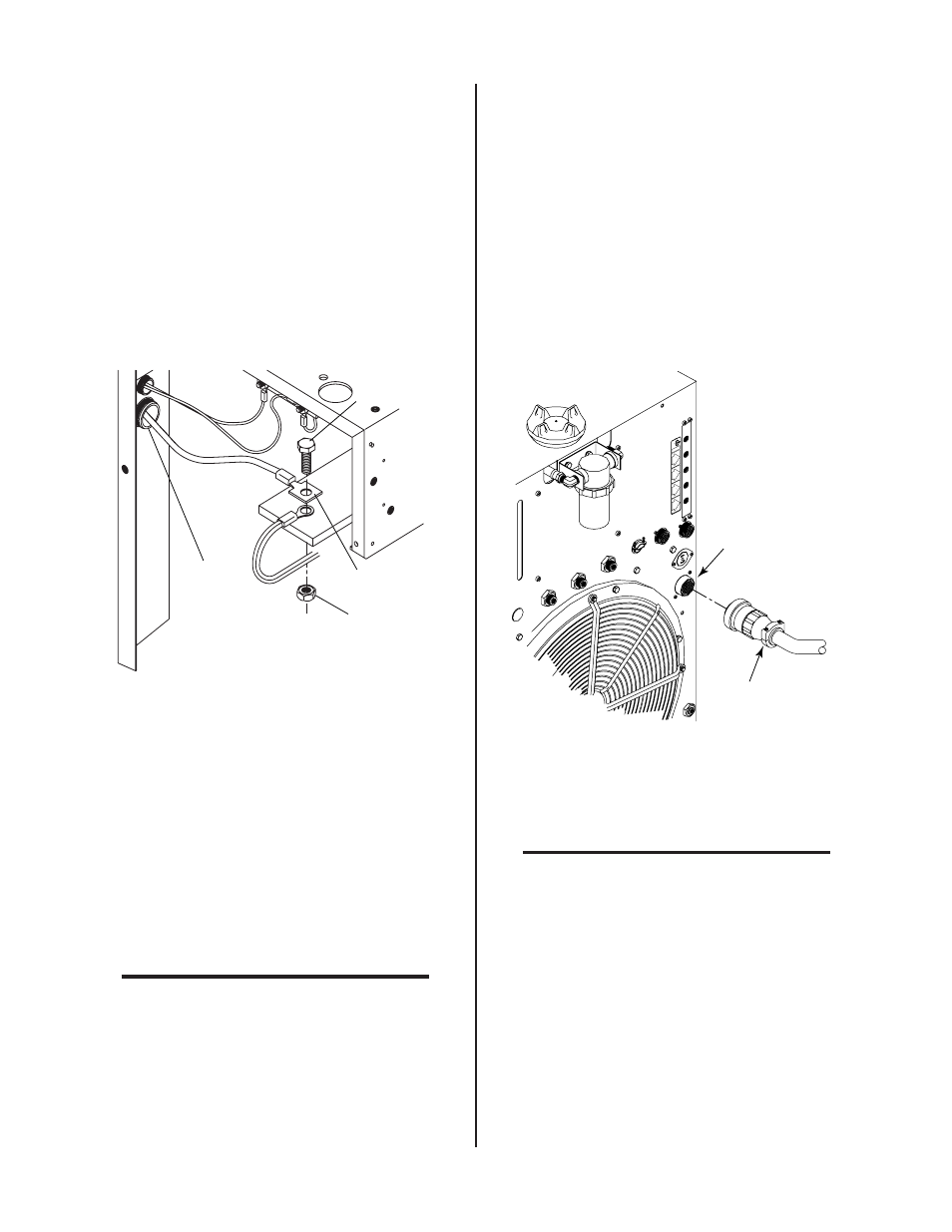
d. Secure the shield lead (black) to the ground connec-
tion with the nut and star washer removed above.
e. Remove the nut and star washer from the other pilot
connection inside the power supply.
f. Secure the pilot lead (red) to the pilot connection with
the nut and star washer removed above.
5. Connect the Power Lead to the Master Power Supply as
follows:
a. Feed the Power Lead through the large strain relief at
the front panel of the Master Power Supply.
b. Remove the lock nut from the power connection termi-
nal inside the power supply.
Large
Strain Relief
Power Lead
Nut
Power Lead
Terminal Bolt
A-01496
Figure 3-21 Power Lead Connection at Master Power
Supply
c. Remove the power lead terminal bolt.
d. Place the Power Lead ring lug over the existing lug.
e. Secure the power lead to the connection with the bolt
and lock nut removed above.
6. Refer to the Arc Starter Box Manual and connect the other
end of the Torch Supply Leads components to the Arc
Starter Box.
7. Refer to the Arc Starter Box Manual and connect the liquid
cooled Maximizer 300 torch to the Arc Starter Box.
NOTE
Refer to the Installation sections in the Maximizer
300 Torch Instruction Manual (0-2573) for more
information on the Torch.
3.12 External Cable Connections
Depending on the options installed there are various cables to
be connected the Power Supply.
A. Optional RC 6010 Remote Control
For mechanized systems, the optional RC 6010 Remote Control
allows the operator to control all system functions from a re-
mote location. The control cable to interface the RC 6010 to the
Power Supply is available in various lengths (Refer to Section
6.04, Options and Accessories).
1. Connect the control cable to the receptacle marked RE-
MOTE CONTROL (J15) on the rear panel of the Power
Supply.
OUTPUT
TO
CONTROL
CONTROL
MODULE
MODULE
AIR
PLASMA
INPUT
INPUT
N
2
PLASMA
PLASMA
INPUT
INPUT
O
2
PLASMA
INPUT
INPUT
PLASMA GAS
PLASMA GAS
Ar/H
Ar/H
2
PLASMA
INPUT
INPUT
A-01505
Cable From
Remote Control
REMOTE CONTROL
Connector (J15)
Figure 3-22 Remote Control Interface Connection
2. Connect the other end of the control cable to the re-
ceptacle marked PS (J37) on the rear panel of the re-
mote control.
NOTE
Refer to the RC 6010 Remote Control Instruction
Manual 0-2478 for more information on the
RC6010 Remote Control including CNC.