Tweco 6000 CE Merlin User Manual
Page 29
Manual 0-2601
3-11
INSTALLATION PROCEDURES
A-01340
Air Filter
Assembly
Shop Air
Gas Input
OUTPUT
OUTPUT
TO
CONTROL
MODULE
AIR
PLASMA
INPUT
INPUT
N2
PLAS
MA
PLASMA
INPUT
INPU
T
O2
PLASMA
PLASMA
INPUT
INPUT
PLASMA GAS
PLASMA GAS
Ar/H
2
PLASMA
INPUT
INPUT
Secondary Air
Gas Fitting
Y-Hose
Assembly
From Supply
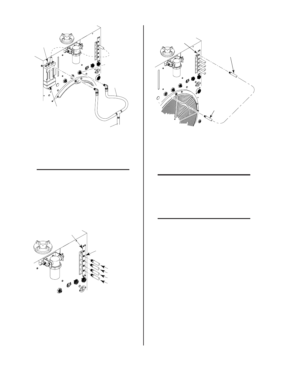
Figure 3-15 Supply Hose Connections Wit Gas Control
Option
10. Apply thread sealer (see NOTE) to the other elbow of the Y-
Hose Assembly.
NOTE
Do Not use teflon tape as a thread sealer as small
particles of the tape may break off and cause the
small gas passage to be blocked in the torch.
11. Connect the elbow fitting to the SECONDARY (Air)
1/4 NPT fitting.
12. Connect the other required plasma gases to the op-
tional Gas Control gas manifold.
A-01341
OUTPUT
TO
CONTROL
MODULE
MODULE
AIR
PLASMA
INPUT
N
2
PLASMA
INPUT
O
2
PLASMA
INPUT
PLASMA GAS
Ar/H
2
PLASMA
INPUT
N2
Gas Control Plasma
Gas Manifold
Air (Filtered)
O
2
Ar/H2
Plasma Gas
Input Fittings
Figure 3-16 Plasma Gas Connections
13. Connect the Plasma Hose from the Plasma Gas Con-
trol Manifold to the Plasma (Air) Gas Input Fitting at
the rear of the Power Supply.
OUTPUT
OUTPUT
TO
CONTROL
CONTROL
MODULE
MODULE
AIR
PLASMA
PLASMA
INPUT
INPUT
N2
PLASMA
PLASMA
INPUT
INPUT
O2
PLASMA
PLASMA
INPUT
INPUT
PLASMA GAS
PLASMA GAS
Ar/H
2
PLASMA
PLASMA
INPUT
INPUT
To Plasma Gas
Input Fitting
Plasma Gas Output
From Gas Select Option
A-01343
Gas Control Option
Gas Manifold
Figure 3-17 Plasma Hose Connection From Gas Control
14. Connect the required secondary gases the SECONDARY
INPUT fittings marked OTHER, N2, and SECONDARY GAS
(air).
NOTE
If air is to be used as the secondary gas it should
be connected to the fitting marked SECONDARY
GAS.
If using Secondary Water connect as described in
paragraph 'C' above.
NOTE
DO NOT connect Secondary Water to the
'OTHER' secondary gas fitting.