Rudder and elevator linkage installation – E-flite RV-9 450 ARF User Manual
Page 9
9
E-flite RV-9 450 Assembly Manual
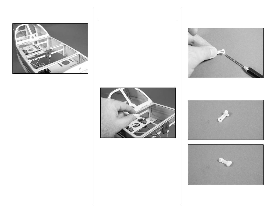
9. Use scissors to cut another small piece of hook
and loop material to mount the remote receiver in
the fuselage as shown.
Rudder and Elevator Linkage
Installation
Required Parts
Fuselage assembly
Nylon pushrod connector (2)
Transmitter
Flight Battery
Speed control or sperate Receiver battery
16
1
/
2
-inch (420mm) elevator pushrod
17
3
/
4
-inch (450mm) rudder pushrod
Pushrod connector backplate (2)
2mm x 5mm machine screw (2)
Required tools
Pin drill
Drill bit: 1/16-inch (1.5mm)
Ruler
Phillips screwdriver: #00, #1
1. Use a #00 Phillips screwdriver to remove the
servo horns from the rudder and elevator servos.
2. Use a pin drill and 1/16-inch (1.5mm) drill bit to
enlarge the outer hole that is 1/2-inch (13mm) from
the center of the servo horn. Secure the pushrod
connector using a pushrod connector backplate.
3. Insert the nylon pushrod connector in the hole
enlarged in the last step. Use pliers to press the
backplate onto the connector.
4. Repeat Steps 2 and 3 to prepare a second
servo horn.
- Habu 32x DF ARF (84 pages)
- A6M5 Zero 300 BNF Basic (17 pages)
- Hawker Sea Fury 480 ARF (28 pages)
- Mystique RES 2.9m ARF (52 pages)
- Super Cub 25e ARF (48 pages)
- AT-6 Texan 25 ARF (52 pages)
- LR-1A Pogo ARF 15e (21 pages)
- J-3 Cub 450 (40 pages)
- Hawker Hurricane 25e PNP (26 pages)
- Hawker Hurricane 25e PNP addendum (1 page)
- Apprentice 15e PNP (28 pages)
- Sukhoi SU-26m 480 ARF (28 pages)
- Beechcraft Bonanza 15e ARF (60 pages)
- Byp Yak 3D ARF (40 pages)
- Ultimate Fx 3D ARF (40 pages)
- Tribute FX 3D ARF (28 pages)
- Sobre 3D Profile (32 pages)
- Ascent EP Park Glider ARF (23 pages)
- Float Set Complete: Carbon-Z Cub (2 pages)
- Carbon-Z Cub PNP (27 pages)
- Carbon-Z Cub PNP Addendum (1 page)
- BAe Hawk 15 DF ARF (36 pages)
- Edge 540QQ 280 BNF Basic (19 pages)
- P-40 Warhawk 300 ARF (20 pages)
- Hawker Sea Fury 400 ARF (40 pages)
- Clipped Wing Cub 250 ARF (40 pages)
- T-34 Mentor 25e ARF (28 pages)
- Ultra Stick 25e ARF (40 pages)
- Ultra Stick 25e ARF Programming Guide (5 pages)
- Slick 3D 480 ARF (48 pages)
- PT-19 450 ARF (44 pages)
- Extra 330SC BP 3D ARF (40 pages)
- Cap 232 BP ARF (44 pages)
- Brio 10 ARF (56 pages)
- Park 480 BL Motor Combo (4 pages)
- Mini Edge 3D ARF (44 pages)
- Cessna 182 370 ARF (32 pages)
- Cessna 182/Park 400 BL Motor Combo (4 pages)
- Tribute 3D Profile ARF (40 pages)
- Fokker DVII 250 ARF (28 pages)
- Enticement F3P ARF (36 pages)
- Carbon-Z Yak 54 3X BNF Basic (23 pages)
- Carbon-Z Scimitar PNP (28 pages)
- UMX B-17G Flying Fortress BNF (18 pages)
- UMX Sbach 342 3D BNF Basic (17 pages)