Aileron servo and linkage installation – E-flite RV-9 450 ARF User Manual
Page 11
11
E-flite RV-9 450 Assembly Manual
11. Use a 16
1
/
2
-inch (406mm) elevator pushrod
wire and repeat Steps 7 through 10 for the
elevator linkage.
Aileron Servo and Linkage Installation
Required Parts
Wing panel (left and right)
Servo with hardware (2)
Nylon pushrod connector (2)
Pushrod connector backplate (2)
2mm x 5mm machine screw (2)
Aileron servo cover (right and left)
12-inch (305mm) servo extension (2)
2mm x 6mm sheet metal screw (8)
Speed control or separate receiver battery
Transmitter
Flight battery
Control horn (2)
Clevis (2)
Clevis retainer (2)
2
3
/
8
-inch (60mm) aileron pushrod (2)
Required tools
Pin drill
Drill bit: 1/16-inch (1.5mm)
Pencil
Phillips screwdriver: #00, #1
Medium CA
Thin CA
Side cutters
Hobby knife with #11 blade
Felt-tipped pen
Rubbing alcohol
Paper towel
Medium grit sandpaper
String, dental floss or commercially available servo
connector (2)
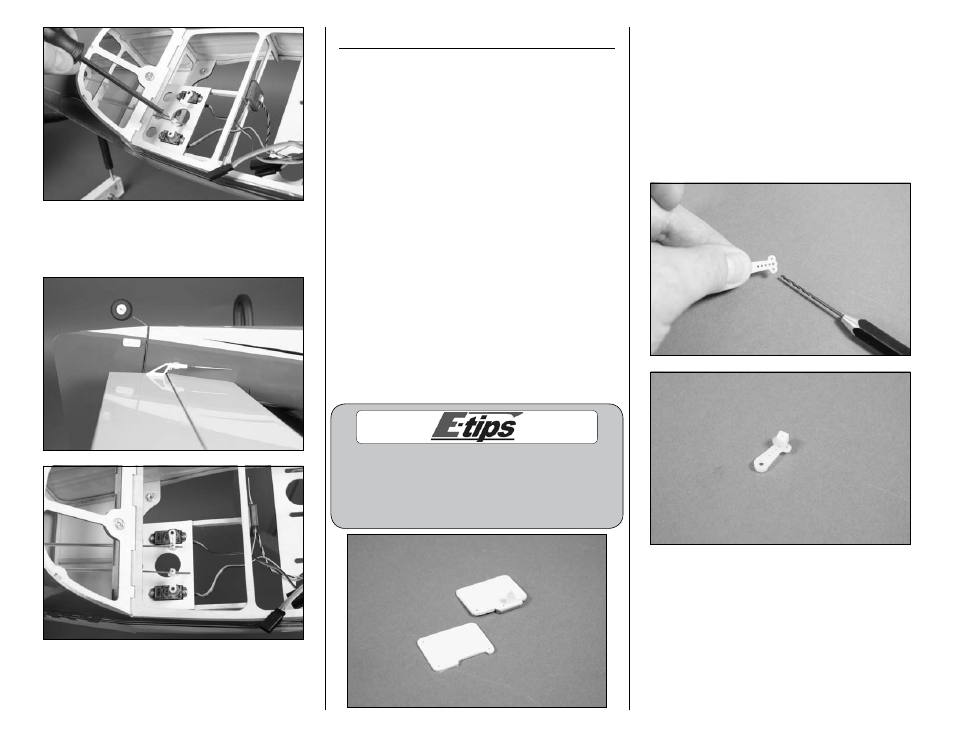
Before starting the aileron servo installation, make sure
to set aside the covers for the flap servo installation
(both operational and fixed) as shown in the photo
below. It is possible that you could accidentally prepare
two identical aileron servos using the flap servo cover.
1. Use a #00 Phillips screwdriver to remove the
servo horns from the aileron servos. Use a pin
drill and 1/16-inch (1.5mm) drill bit to enlarge
the outer hole that is 1/2-inch (13mm) from the
center of the servo horn. Secure the pushrod
connector using a pushrod connector backplate.
Insert the nylon pushrod connector in the hole
enlarged in the last step. Use pliers to press the
backplate onto the connector. Prepare both aileron
servo horns at this time.