Operational flap linkage installation – E-flite RV-9 450 ARF User Manual
Page 20
20
E-flite RV-9 450 Assembly Manual
Operational Flap Linkage Installation
Required Parts
Wing assembly
Flap linkage
Clevis (2)
Clevis retainer (2)
Flap control horn (2) Flap servo cover
Servo with hardware 2mm x 5mm machine screw
Transmitter
Fuselage assembly
Flight battery
Speed control or separate receiver battery
Connector backplate
Nylon pushrod connector
2mm x 6mm sheet metal screw (4)
Required tools
Pliers
Phillips screwdriver: #1
Pin drill
Drill bit: 1/16-inch (1.5mm)
Thin CA
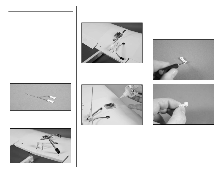
1. Locate two clevises and clevis retainers. Slide the
retainers onto the clevises. Thread the clevises on
the flap linkage 16 turns.
2. Thread the flap control horns on the flap control
rods until the top of the horn is aligned with the top
of the threaded rod.
3. Connect the clevises from the flap linkage to the
flap control horns. Do not slide the clevis retainers
into position as the clevises may require adjustment
to position the flaps properly.
4. Apply 2–3 drops of thin CA into each hole to
harden the surrounding wood. This provides a
harder surface, making the screws more secure
when installed.
5. Use a #00 Phillips screwdriver to remove the
servo horn from the flap servo. Use a pin drill
and 1/16-inch (1.5mm) drill bit to enlarge the
outer hole that is 1/2-inch (13mm) from the center
of the servo horn. Secure the pushrod connector
using a pushrod connector backplate. Insert the
nylon pushrod connector in the hole enlarged in
the last step. Use pliers to press the backplate onto
the connector.