Specifications – Banner Safety Mat Monitoring Modules User Manual
Page 6
1. Remove power to the machine control elements, if it is already connected.
2. Apply force to the mat’s sensing area, using a test piece as outlined in the mat manufacturer’s literature, or the appropriate standard.
3. Apply input power to the Safety Mat Monitor Module at terminals A1 and A2 or B1 and B2. Verify that only the Power indicator LED is ON.
4. Remove the test piece from the safety mat (clear the mat sensing area).
5. Manual Reset mode: Ch1 and Ch2 indicators should be flashing. Close and reopen the Reset switch.
6. Verify that the Ch1 and Ch2 indicators both come ON. If only one indicator comes ON or if any indicator is flashing, refer to the Troubleshooting section for more
information. Return to step 2 after correcting the problem.
7. Apply force in several locations (using a test piece) to the mat’s sensing area, per the mat manufacturer’s recommendations. Verify that the Ch1 and Ch2 indicators
turn OFF simultaneously. If either indicator does not go OFF, disconnect the input power and check all wiring. Return to step 2 after correcting the problem.
8. Repeat for each safety mat individually.
9. Close and secure the enclosure. Apply power to the machine control elements and perform the following Periodic Checkout Procedure.
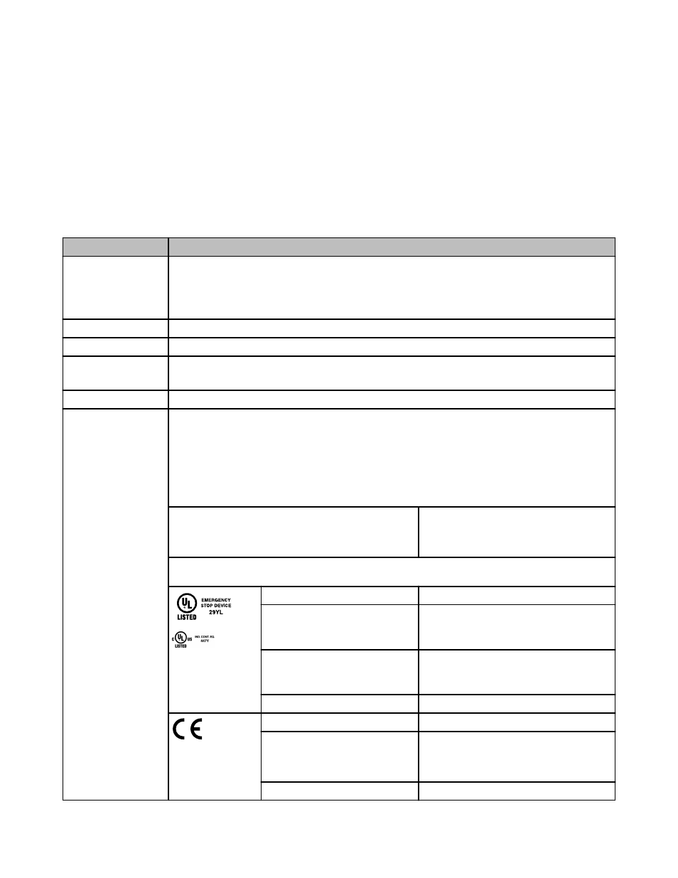
Specifications
Category
Specification
Supply Voltage and Current
AI-A2: 115V ac (model SM-GA-5A) or 230V ac (model SM-HA-5A) ±15%, 50/60Hz
BI-B2: 11V dc – 27.6V dc
Connect the Safety Module only to a SELV (safety extra-low voltage, for circuits without earth ground) or a PELV (protected extra-low
voltage, for circuits with earth ground) power supply, according to EN IEC 60950, NEC Class 2.
Power Consumption
Approx. 4W/7VA
Supply Protection Circuitry
Protected against transient voltages and reverse polarity
Overvoltage Category
Output relay contact voltage of 1V to 150V ac/dc: category III
Output relay contact voltage of 151V to 250V ac/dc: category III, if appropriate overvoltage reduction is provided, as described earlier.
Pollution Degree
2
Relay Outputs
4 normally open (N.O.) output channels and 1 normally closed (N.C.) output
Each normally open output channel is a series connection of contacts from two forced-guided (mechanically linked) relays, K1-K2. The
normally closed Aux. output channel is a parallel connection of contacts from two forced-guided relays, K1-K2.
Contacts: AgNi, 5 μm gold-plated
Low Current Rating: The 5 μm gold-plated contacts allow the switching of low current/low voltage. In these low-power applications, multi-
ple contacts can also be switched in series (e.g., “dry switching”). To preserve the gold plating on the contacts, do not exceed the follow-
ing max. values at any time:
Min. voltage: 1V ac/dc
Min. current: 5 mA ac/dc
Min. power: 5 mW (5 mVA)
Max. voltage: 60V
Max. current: 300 mA
Max. power: 7 W (7 VA)
High Current Rating: If higher loads must be switched through one or more of the contacts, the minimum and maximum values of the
contact(s) changes to:
Minimum
Maximum
Voltage: 15V ac/dc
N.O. Safety Contacts (13-14, 23-24, 33-34, 43-44): 250V
ac / 24V dc, 6A resistive
B300, Q300 (UL508)
Current: 250 mA ac/dc
N.C. Auxiliary Contact (51-52): 250V ac / 24V dc, 5A resis-
tive
B300, Q300 (UL508)
Power: 5 W (5 VA)
Minimum
Maximum — IEC60947-5-1
Voltage: 15V ac/dc
N.O. Safety Contacts:
AC-1: 250V ac, 6A; DC-1: 24V dc, 6A
AC-15: 230V ac, 3A; DC-13: 24V dc, 4A
Current: 250 mA ac/dc
N.C. Auxiliary Contact:
SM-xA-5A Safety Mat Monitoring Modules
6
www.bannerengineering.com - tel: 763-544-3164
P/N 122364 rev. C