Mechanical installation, Electrical installation – Banner Safety Mat Monitoring Modules User Manual
Page 2
Multiple mats may be switched in series to one Safety Module. The Safety Module provides the redun-
dant safety outputs required for creating a control-reliable safety circuit. The Safety Module has two
functions:
• To monitor the conductive elements (plates) and the wiring of one or more safety mat(s) for failures
and prevent the machine from restarting if any mat or the Module fails, and
• To provide a reset routine after the operator steps off the safety mat. This prevents the controlled
machinery from restarting automatically after the mat is cleared. This necessary reset/restart func-
tion is required by ANSI B11 and ANSI NFPA 79 machine safety standards. If the Module is used in
auto-reset mode, the reset/restart function must be provided by the machine control system.
NOTE:
NOTE:The Safety Module is not designed to monitor 2-wire mats,
bumpers, or edges (with or without sensing resistors).
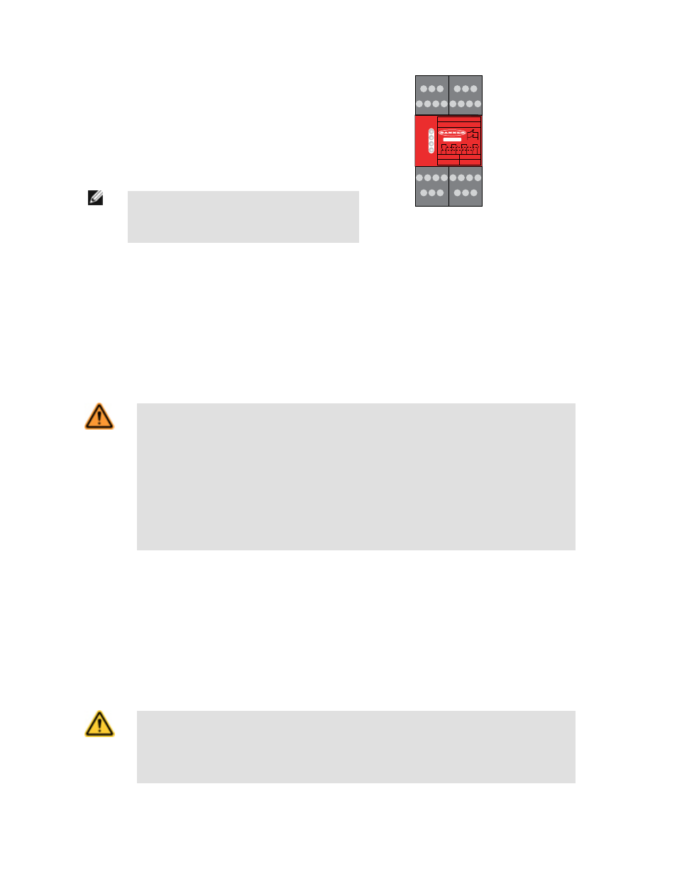
POWER
FAULT
CH. 1
CH. 2
K1
K2
51
52
13 14 23
A1 A2 B1 B2
S11 S12 S21 S22
24
33 34 43 44
Y30 Y31 Y32
Y35 51
52
S31 S32 S33
S34 S32 S35
SM-GA-5A
13
Y30 Y31 Y32
14 23 24 33
Y35 51 52
34 43 44
A1 A2 B1 B2 S11 S12 S21 S22
S31 S32 S33
S34 S32 S35
Figure 1. Indicator and Terminal Locations
In operation, the Safety Module monitors the conductive elements (plates) of the pressure-sensitive mat for shorting of those elements (i.e., when the mat is stepped on)
and certain faults, such as shorts to other sources of power or ground (0V), or open connecting wires. With a +24V dc supply, Channel 1 (S11-S12) supplies > 20V dc that
is pulsed low and Channel 2 (S21-S22) supplies < 2V that is pulsed high; when these two channels are shorted together, the safety output contacts open (13-14, 23-24,
33-34, and 43-44).
If a fault is detected, the Module will lock out, open its safety outputs, and indicate the problem on its LED display, which can be diagnosed by using the troubleshooting
table in this document. After repairing the fault, step on the mat and off it again to clear the lockout condition (or cycle power). If the fault has been cleared and no other
faults exist, the Fault LED turns OFF and the Module can be reset (if configured for Auto Reset, the safety outputs will turn ON immediately).
The output relays energize automatically if the Module is wired for Auto Reset mode, all sensors are clear, all faults are removed or corrected, and power is applied. The
Module requires a manual reset if it is wired for Manual Reset mode.
WARNING: Application of Safety Mats
Requirements vary widely for the level of control reliability or category as described by ISO 13849-1 (EN 954-1) in the application of
safety mats. While Banner Engineering always recommends the highest level of safety in any application, it is the responsibility of
the user to safely install, operate, and maintain each safety system per the manufacturer's recommendations and comply
with all relevant laws and regulations.
Do not use safety mats as a tripping device to initiate machine motion (such as in a presence-sensing device initiation applica-
tion), due to the possibility of unexpected start or re-start of the machine cycle resulting from failure(s) within the mat and the inter-
connect cabling.
Do not use a safety mat to enable or provide the means to allow the machine control to start hazardous motion by simply
standing on the safety mat (e.g., at a control station). This type of application uses reverse/negative logic and certain failures (e.g.,
loss of power to the Module) can result in a "false" enable signal.
Mechanical Installation
Route the mat cable to the Safety Module location. The Safety Module must be installed inside an enclosure. It is not designed for exposed wiring. It is the user’s responsi-
bility to house the Safety Module in an enclosure with NEMA 3 (IEC IP54) rating, or better.
The Safety Module mounts directly to standard 35 mm DIN rail; see Dimensions.
Heat Dissipation Considerations. For reliable operation, ensure that the operating specifications are not exceeded. The enclosure must provide adequate heat dissipa-
tion, so that the air closely surrounding the Module does not exceed the maximum operating temperature stated in the Specifications. Methods to reduce heat build-up
include venting, forced airflow (e.g., exhaust fans), adequate enclosure exterior surface area, and spacing between modules and other sources of heat.
Electrical Installation
CAUTION: Shock Hazard
Always disconnect power from the Banner product and the guarded machine before making any connections or replacing any com-
ponent. Electrical installation and wiring must be made by qualified personnel and must comply with the NEC (National Electrical
Code), ANSI NFPA79 or IEC 60204-1 and -2, and all applicable local standards and codes. Use extreme caution to avoid electri-
cal shock at all times. Serious bodily injury or death could result.
SM-xA-5A Safety Mat Monitoring Modules
2
www.bannerengineering.com - tel: 763-544-3164
P/N 122364 rev. C