Electrical installation, Maintenance/checkout – Banner RP-LM40 Rope Pull Switches User Manual
Page 4
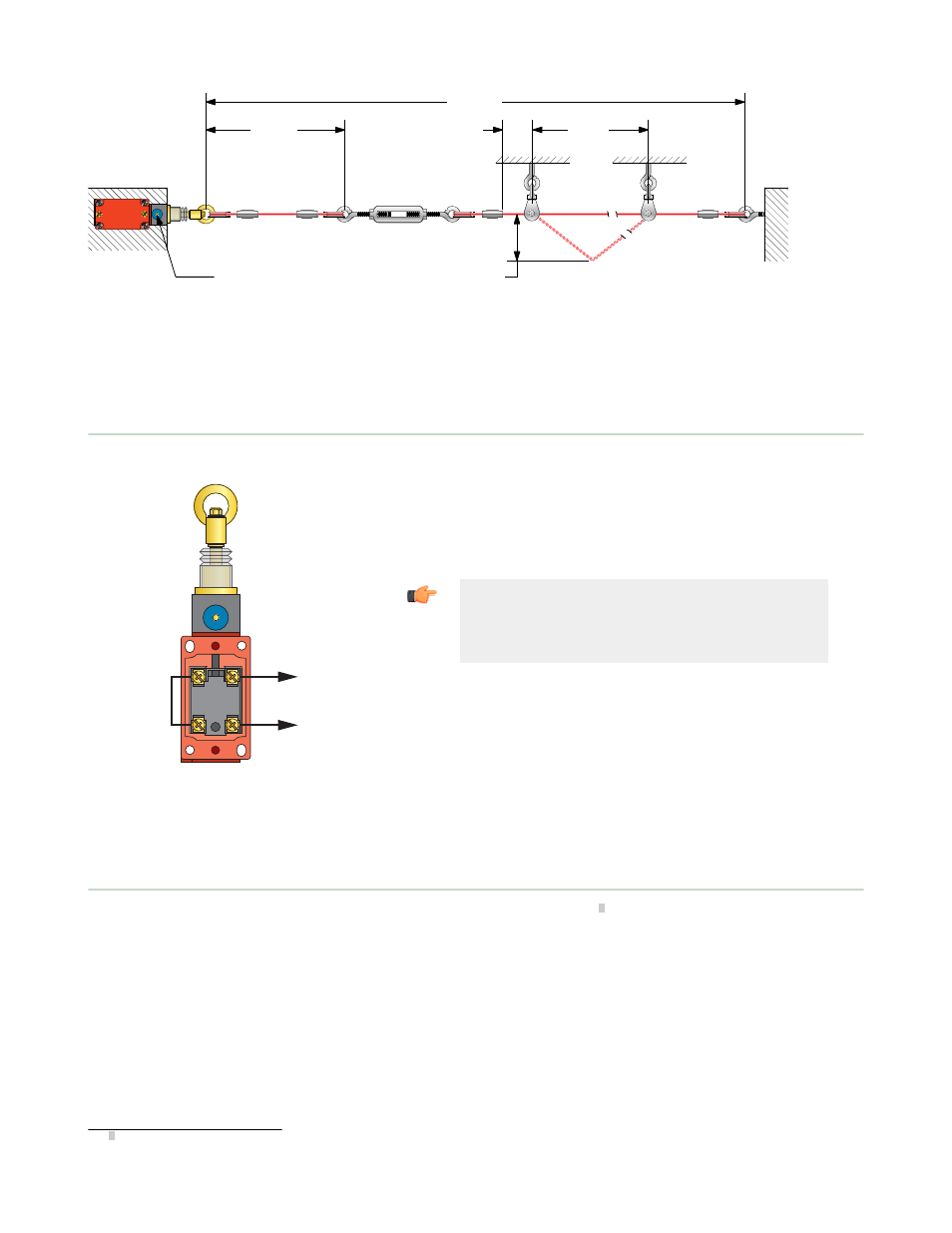
150 mm
(6") max.
6 m
(20') max.
3 m
(10') max.
25 mm
(1") min.
400 mm (16") max.
for Actuation of Switch
NOTE: Force to actuate must not exceed 200 N (45 lbf)
Reset Button—
Pull to Reset
Figure 4. Assembly of Rope and Hardware
All hardware is supplied by the user. The switch mounting holes are on a standard limit switch mounting pattern of 30 x 60
millimeters, and accept M5 (#10) hardware. Wire rope and associated hardware may be ordered separately; see
Accessories.
Electrical Installation
Install
Jumper Wire
Between
Contacts
13
25
14
26
To
Machine
Control
Stop
Circuit
Figure 5. Wire the two switch contacts in series
Access to the Wiring Chamber. The wiring chamber is accessed via a
cover plate (remove two screws). A conduit adapter is supplied to convert
the 20 millimeter threaded entrance to 1/2" NPT. An accessory cable gland
which fits the M20 thread is also available.
Wiring. Install a jumper wire to place the two switch contacts in series, as
shown.
Important: Model RP-LM40D-6 does not latch contacts
25–26 open when the rope is pulled. The contacts close
when the rope is released. When using model RP-
LM40D-6, a latch circuit must be included in the
machine control circuitry.
Maintenance/Checkout
At switch installation or replacement and at machine set up, a Designated Person
1
must test each switch for proper
machine shutdown response and check the switch(es) and installation for proper operation, physical damage, mounting
(looseness), and excessive environmental contamination. This must also take place on a periodic schedule determined by
the user, based on the severity of the operating environment and the frequency of switch actuations. Adjust, repair, or
replace components as needed. If inspection reveals contamination on the switch, thoroughly clean the switch and
eliminate the cause of the contamination. Replace the switch and/or appropriate components when any parts or
assemblies are damaged, broken, deformed, or badly worn; or if the electrical/mechanical specifications (for the
environment and operating conditions) have been exceeded. Always test the control system for proper functioning under
machine control conditions after performing maintenance, replacing the switch, or replacing any component of the switch.
Additional items that should be included in the checkout and/or regularly scheduled maintenance of a rope pull system:
•
Check for proper rope tension and adjust as needed
•
Verify free operation (no binding) of the rope and proper tripping when the rope is pulled
•
Periodically lubricate the pulleys and other moving parts associated with the rope
1 A Designated Person is identified in writing by the employer as being appropriately trained to perform a specified checkout procedure.
RP-LM40 Series Rope Pull Switches
4
www.bannerengineering.com - tel: 763-544-3164
P/N 62082 Rev. C