Mechanical installation – Banner RP-LM40 Rope Pull Switches User Manual
Page 3
WARNING: Not a Safeguarding Device
An Emergency Stop Device is not considered a safeguarding device because it requires an
overt action by an individual to stop machine motion or hazards.
A safeguarding device limits or eliminates an individual's exposure to a hazard without action by the
individual or others. Because an individual must actuate the device for it to function, these devices do
not fit the definition of a safeguarding device and cannot be substituted for required safeguarding. Refer
to the relevant standards to determine those requirements.
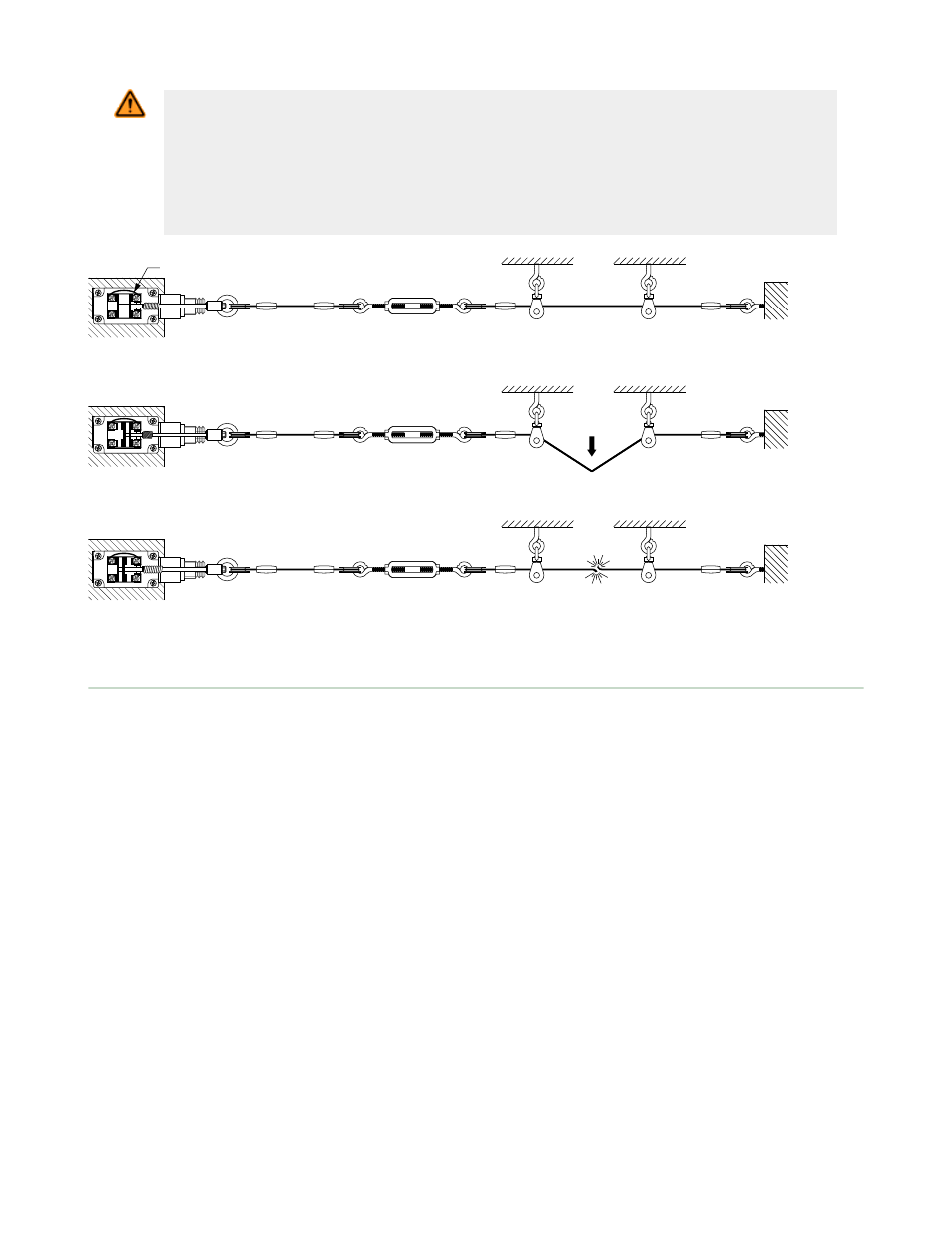
Wire in Series
Figure 1. Run Position: Proper Rope Tension
Figure 2. Rope Pulled: Contact 25-26 Opens
Figure 3. Rope Break or Slack: Contact 13-14 Opens
Mechanical Installation
Installation Guidelines
•
The rope should be easily accessible and visible along its entire length. Markers or flags may be fixed on the rope
to increase its visibility
•
Mounting points, including support points, must be rigid and allow sufficient space around the rope to allow easy
access
•
The rope should be free of friction at all supports. Pulleys are recommended
•
Use only pulleys (not eye bolts) when routing the rope around a corner or whenever direction changes, even
slightly
•
Never run rope through conduit or other tubing
•
Never attach weights to the rope
•
Temperature affects rope tension. The rope expands (lengthens) when temperature increases, and contracts
(shrinks) when temperature decreases. Significant temperature variations require frequent checks of the tension
adjustment
•
Do not exceed the maximum specified total rope length. Banner offers models for other spans; contact Banner
Engineering or visit
www.bannerengineering.com
for model selection
Installation Procedure
1. Mount the switch securely on a solid, stationary surface.
2. Fasten an eye bolt at the opposite end of the rope span, up to 6 m (20 ft) from the switch. The anchor for the eye
bolt also must be solid and stationary, to withstand the constant tension of the rope.
3. Assemble the rope as shown. Keep the rope’s PVC cover intact along its complete length.
4. Use pulleys (recommended) or eye bolts at each support point. A pulley must be used when routing the rope
around a corner, regardless of the angle.
5. Connect a continuity tester (or ohmmeter) between terminals 25–26 of the switch. Adjust the turnbuckle to tighten
the rope, until contact 25–26 closes. This indicates sufficient rope tension.
6. Pull hard on the rope several times. If contact 25–26 remains open (following reset, for model RP-LM40D-6L),
further tighten the turnbuckle, until contact 25–26 closes.
7. Repeat step 6 until contact 25–26 remains closed for the Run condition.
RP-LM40 Series Rope Pull Switches
P/N 62082 Rev. C
www.bannerengineering.com - tel: 763-544-3164
3