Banner DUO-TOUCH SG Two-Hand Control Safety Modules User Manual
Page 11
STB2
Brown
Yell ow
Yell ow
Black
Black
Blue
Whit e
Whit e
Z1
Z2
S12
S11
S13
S22
S21
S23
STB1
AT-GM- 11K M
AT-HM- 11K M
+ –
+ –
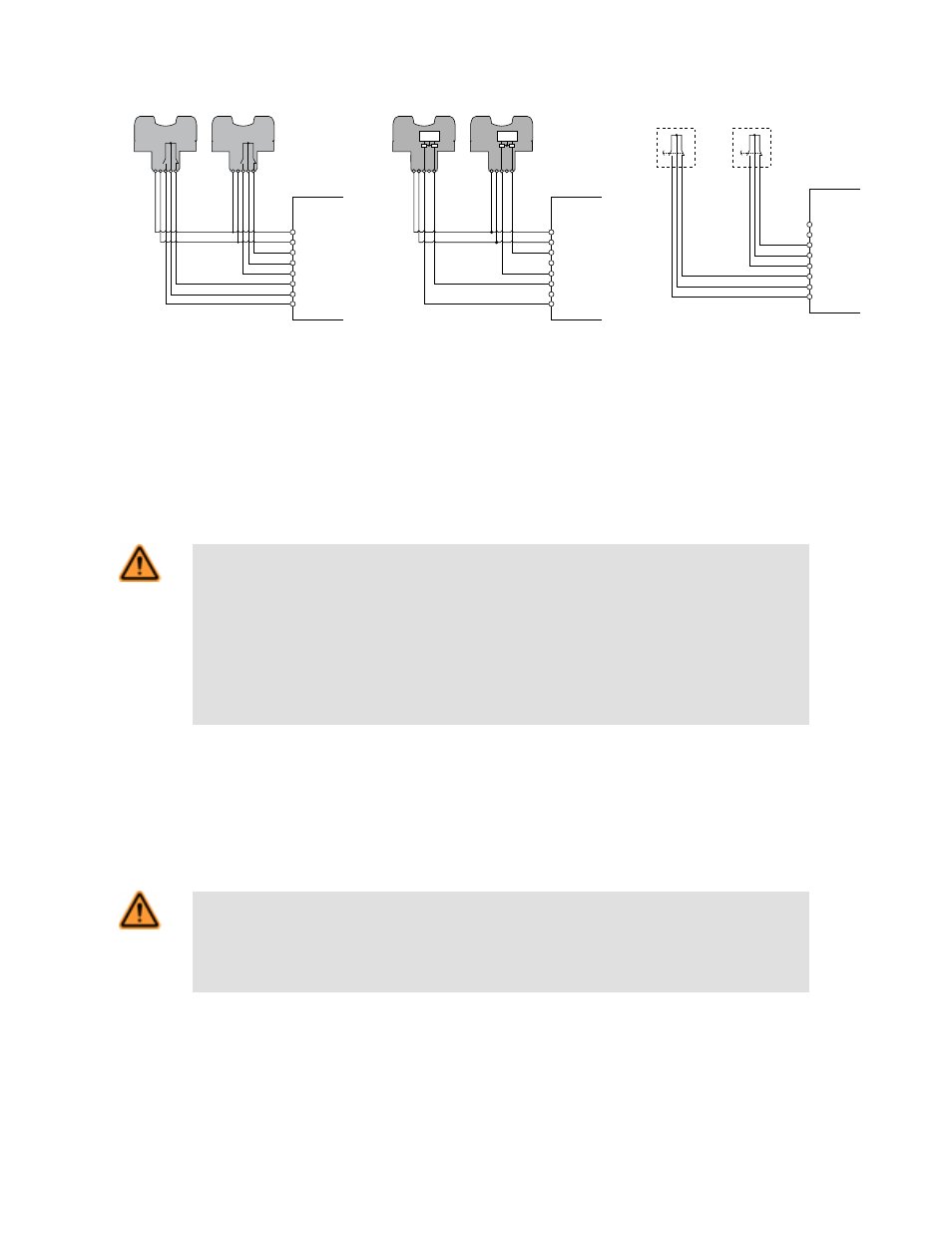
Figure 8. Hookup to two STB touch but-
tons with contact outputs
Logic
STB2
+ –
STB1
+ –
Logic
Brown
Black
Black
Blue
Whit e
Whit e
Z1
Z2
S12
S11
S13
S22
S21
S23
AT-GM- 11K M
AT-HM- 11K M
Figure 9. Hookup to two STB touch but-
tons with PNP (sourcing) outputs
Z1
Z2
S12
S11
S13
S22
S21
S23
AT-GM- 11K M
AT-HM- 11K M
SW2
SW1
Figure 10. Hookup to two mechanical
push buttons with contact outputs
Connection of Input Switches
The actuation devices are connected to the DUO-TOUCH SG module as shown in Figures 8, 9, and 10. SW1 and SW2 must both have
normally open and normally closed output contacts, or two current-sourcing complementary outputs each, all capable of reliably switching
up to 20 mA, at 12V dc. If hand controls have metal housings, the housings must be connected to protective earth ground.
If STB Touch Buttons are used, connect the brown and blue wires to terminals Z1 and Z2. If electronic actuation devices other than STB
Touch Buttons are used, they must share the same voltage supply with the Safety Module.
WARNING: Use of Electronic Hand Controls
Electronic (powered) hand controls include optical touch buttons, capacitive touch buttons and similar de-
vices. When electronic hand controls are used as input switches for a Safety Module, the hand con-
trols and the Safety Module must be powered from the same voltage source. Failure to do so cre-
ates a potentially dangerous condition, which could result in serious injury or death.
If power is applied to the Safety Module before power is applied to the electronic hand controls, an output
from the Safety Module could result and may trigger machine motion. Also, electronic hand controls can-
not guarantee the state of their outputs at the time power is applied to them.
Connection of Power to the DUO-TOUCH SG Safety Module
The Safety Module requires a 24V dc, 115V ac or 230V ac supply voltage (see
on page 15 ). Use extreme caution
whenever installing ac power. Use a minimum of 16 to 18 AWG wire for power and output connections. A hand-operated supply discon-
nect (e.g. a circuit breaker) must be provided (per NFPA79 and IEC/EN60204).
Connection to the Machine to be Controlled
WARNING: Interfacing Safety Outputs
NEVER wire or interface an intermediate device (e.g., PLC, PES, PC) that can fail in such a manner
that there is a loss of the safety stop command to the MPCEs.
To do so could result in serious bodily injury or death.
Figure 11 shows a generic connection of the Safety Module’s two redundant output contacts to machine primary control elements
MPCE1 and MPCE2. An MPCE is defined as an electrically-powered element, external to the safety module, which directly controls the
machine’s normal operating motion so that it is the last (in time) to operate when motion is either initiated or arrested. Some older ma-
chines offer only one MPCE; for such machines, it may be necessary to add a second MPCE to establish the appropriate level of safety
integrity (e.g., control reliability).
DUO-TOUCH® SG Two-Hand Control Modules
P/N 109782 Rev.B
www.bannerengineering.com - tel: 763-544-3164
11