Specifications – Banner Interface Modules User Manual
Page 7
Models SC-IM9.. – Safety Controller Interface Modules
P/N 131845
7
Banner Engineering Corp. • Minneapolis, MN U.S.A.
www.bannerengineering.com • Tel: 763.544.3164
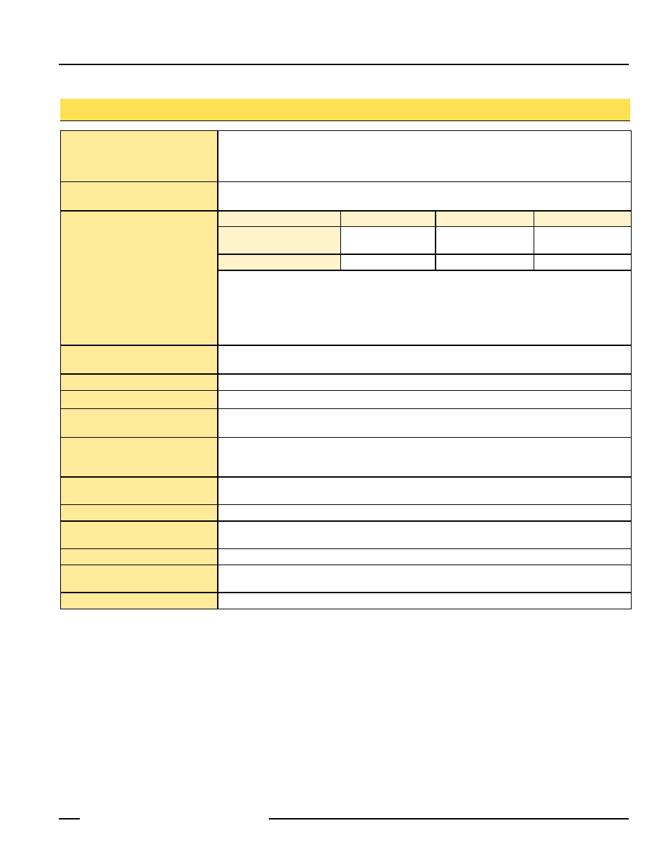
Input Voltage and Current
24V dc, +/-15% no polarity, supplied by Safety Controller
Operating voltage limits
Pick-up: (0.7−1.15) x Un
Drop-out: (0.1−0.2) x Un
Average Consumption at 20° C
(In-Rush Holding)
3.2 W
Output Configuration
SC-IM9A
SC-IM9B
SC-IM9C
Number of Redundant
N.O. Contacts
1 x 3
2 x 3
3 x 3
Number of N.C. Contacts
1 x 1
2 x 1
3 x 1
Min. switching voltage: 1V ac/dc
Max. switching voltage: 575V
Min. switching current: 30 mA ac/dc
Max. switching current: 10A ac/dc
Min. switching power: 50 mW (50 mVA)
Max. switching power: 275 W (7200 VA)
Mechanical life: 20,000,000 operations
Electrical life (AC3): 500,000 cycles @ 10 A
3,800,000 cycles @ 2 A
Conventional Free Air Thermal
Current Ith (≤ 40° C)
10A
Rated Insulation Voltage (Ui)
690V
Frequency Limit
25−40 Hz (derating for use at 61−400 Hz)
Terminal Tightening Torque
Min/Max
0.8−1 Nm (0.59−0.74 lbft)
Max Wire Gauge
(for 1 or 2 Wires)
18−12 AWG
Flexible w/o Ferrule: 0.75−2.5 mm²
Flexible w/Ferrule: 2 x 1 or 1 x 2.5 mm²
Output Response Time
N.O. contacts 13–14, 33–34, 43–44: 18–25 ms closing, 3 ms opening
N.C. contacts 21–22: 3-5 ms closing, 17 ms opening
Status Indicators
Output ON/OFF indicator on the front of each contactor; see Figure 1.
Environmental Rating
Rated NEMA 1, IEC IP20.
Interface Module must be installed inside an enclosure rated IEC IP54, or better.
Mounting
Mounts to standard 35 mm DIN-rail track. Must mount adjacent to Safety Controller.
Operating Conditions
Temperature: –40° to +60° C (–40° to 122° F) operating, –55° to +70° C (–40° to 122° F) storage
Max. Relative Humidity: 90% @ 50° C (non-condensing)
Application Notes
There are no adjustments and no user-serviceable parts.
Specifications