Banner QMT72 Rope Pull Switches User Manual
Page 5
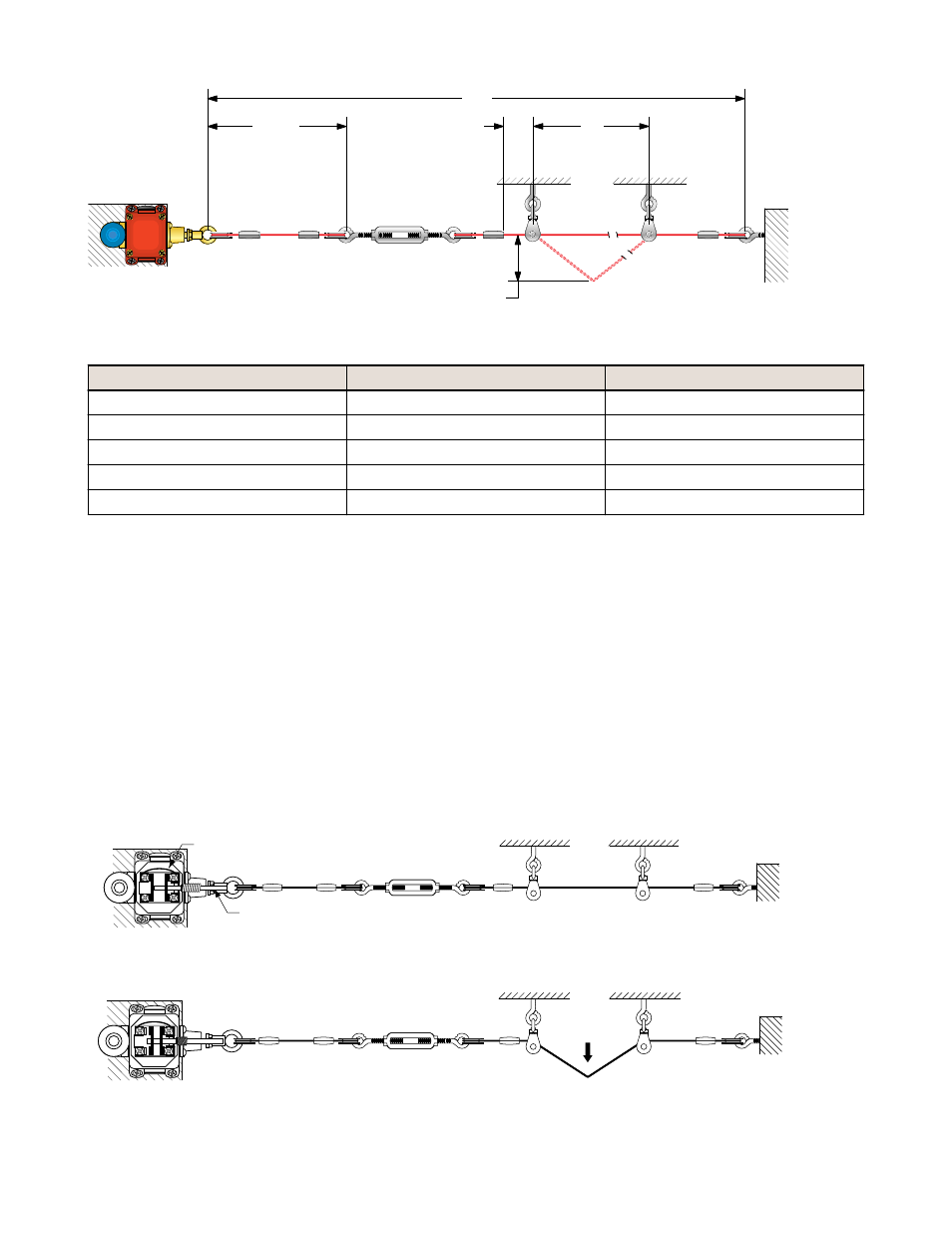
150 mm
(6") max.
L1
L2
25 mm
(1") min.
400 mm (16") max.
for Actuation of Switch
NOTE:
Force to actuate must
not exceed 200 N (45 lbf)
Figure 2. Assembly of Rope and Hardware
Model
Max. Total Length L1
Max. Distance Between Pulleys L2
RP-QM72D-6L
6 m (20 ft)
3 m (10 ft)
RP-QM72D-12L
12 m (40 ft)
4 m (13 ft)
RP-QMT72D-20L
20 m (66 ft)
5 m (17 ft)
RP-QMT72E-12L
12 m (40 ft)
4 m (13 ft)
RP-QMT72F-12L
12 m (40 ft)
4 m (13 ft)
Installation Procedure
1. Mount the switch securely on a solid, stationary surface.
2. Fasten an eye bolt at the opposite end of the rope span, up to 6 m (20 ft), or 12 m (40 ft) or 20 m (66 ft) from the
switch, depending on model. The anchor for the eye bolt also must be solid and stationary, to withstand the
constant tension of the rope.
3. Assemble the rope, as shown. Keep the rope’s PVC cover intact along its complete length.
4. Use pulleys (recommended) or eye bolts at each support point. A pulley must be used when routing the rope
around a corner, regardless of the angle.
5. Apply tension to the rope using the turnbuckle until the indicator mark on the switch aligns with the leading edge of
the housing flange. This indicates sufficient rope tension. (Contacts 25/26, and 45/46, if applicable, will close.)
6. Pull hard on the rope and reset the latch several times. If contact 25/26 (45/46) remains open following the reset,
further tighten the turnbuckle, until contact 25/26 (45/46) closes.
7. Repeat step 6 until contact 25/26 (45/46) remains closed for the Run condition.
All hardware is supplied by the user. The switch mounting holes are on a mounting pattern of 72 x 40 or 72 x 76
millimeters, and accept M5 (#10) hardware. Wire rope and associated hardware may be ordered separately; see
Accessories.
Wire in Series
Tension Indicator Mark
Figure 3. Run Position: Proper Rope Tension
Figure 4. Rope Pulled: Contact 25/26 (45/46) Opens
Rope Pull Switches
P/N 62084 Rev. C
www.bannerengineering.com - tel: 763-544-3164
5