Banner QMT72 Rope Pull Switches User Manual
Page 2
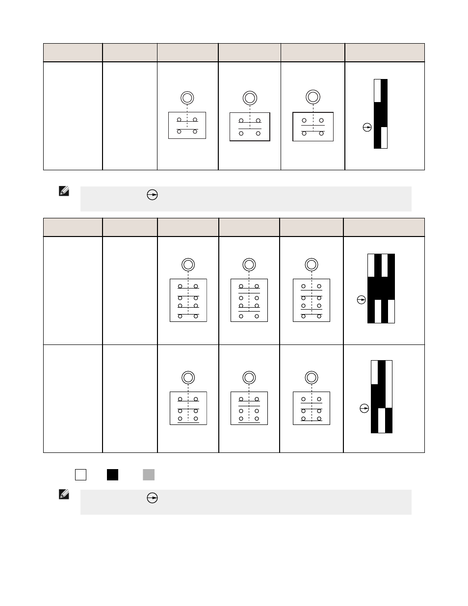
Model
Max. Rope
Length
Run Position
Cable Pulled
Cable Break
Switching Diagram
RP-QMT72D-20L
20 m (65 ft)
25
26
13
14
25
26
13
14
25
26
13
14
13-14
25-26
Break
Pull
50N
180N
0 (0)
2 (0.08)
11 (0.43)
13 (0.51)
mm (in)
NOTE: This symbol
for a positive-opening safety contact (IEC 60947-5-1) is used in the switching
diagram to identify the point in actuator travel where the normally-closed safety contact is fully open.
Model
Max. Rope
Length
Run Position
Cable Pulled
Cable Break
Switching Diagram
RP-QMT72F-12L
12 m (40 ft)
25
26
45
46
13
14
33
34
25
26
45
46
13
14
33
34
25
26
45
46
13
14
33
34
26
14
13-14
25-26
Break
Pull
80N
200N
0 (0)
2 (0.08)
6 (0.24)
8 (0.32)
mm (in)
33-34
45-46
Break
Pull
RP-QMT72E-12L
12 m (40 ft)
25
26
13
14
33
34
25
26
13
14
33
34
25
26
13
14
33
34
13-14
25-26
Break
Pull
80N
200N
0 (0)
2 (0.08)
6 (0.24)
8 (0.32)
mm (in)
33-34
AUX
Contacts:
Open
Closed
Transition
NOTE: This symbol
for a positive-opening safety contact (IEC 60947-5-1) is used in the switching
diagram to identify the point in actuator travel where the normally-closed safety contact is fully open.
Rope Pull Switches
2
www.bannerengineering.com - tel: 763-544-3164
P/N 62084 Rev. C