Connection to the machine to be controlled – Banner Interface Modules User Manual
Page 6
EDM
Safety Output
+24V dc
0V dc
+
+
14
23
24
33
34
Machine
Control
Feedback (optional)
IM-T-9A
Primary
Safety
Device
MPCE
1
MPCE
2
MPCE2
MPCE1
Y2
Y1
Y3
Y4
S4
K2
S3
S1
K1
K2
K1
S2
13
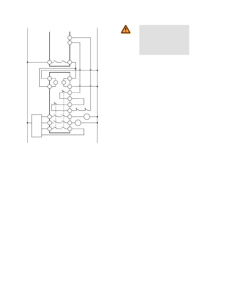
Figure 7. Generalized hookup to a primary safety device with
one redundant relay safety output (one-channel control) and
one monitoring input.
WARNING: Single-Channel Hook-
up. Single-channel hookup, as
shown is only for use when the
PSD and the Interface Module are
within the same enclosure. Refer
to One-Channel Control.
Although this hookup shows model IM-T-9A, the hookup for model
IM-T-11A is identical.
The single-channel input hookup configuration can not detect short circuits to secondary sources of +24V dc or detect the loss of the
switching function of the primary safety device (i.e., it is not redundant) and thus this circuit typically can meet only ISO 13849-1 Category
2.
It is recommended that in all circumstances the installation of the Interface Module and its associated primary safety device are installed
to eliminate or minimize the possibility of failures and faults that could result in the loss of the safety function(s). Methods to eliminate or
minimize the possibility of these failures include, but are not limited to:
• Physically separating interconnecting control wires from each other and from secondary sources of power.
• Routing interconnecting control wires in separate conduit, runs, or channels.
• Locating all elements (modules, switches, and devices under control) within one control panel, adjacent to each other, and directly
connected with short wires.
• Properly installing multi-conductor cabling and multiple wires through strain-relief fittings. (Overtightening of a strain-relief can cause
short circuits at that point.)
• Using positive-opening components as described by IEC 60947-5-1 installed and mounted in a positive mode.
• Periodically checking the functional integrity / safety function and training operators, maintenance personnel, and others associated
with the operation of the machine to recognize and immediately correct such failures.
If you have any questions about your intended use, please contact a Banner applications engineer at the numbers listed on the last page.
Connection to the Machine to be Controlled
The wiring diagrams show a generic connection of two safety output channels of the Interface Module to Machine Primary Control Ele-
ments MPCE1 and MPCE2. A Machine Primary Control Element is an electrically powered device, external to the Interface Module,
IM-T-9A and IM-T-11A Interface Modules
6
www.bannerengineering.com - tel: 763-544-3164
P/N 062822 Rev. D